George Gorton Machine Company rotary table

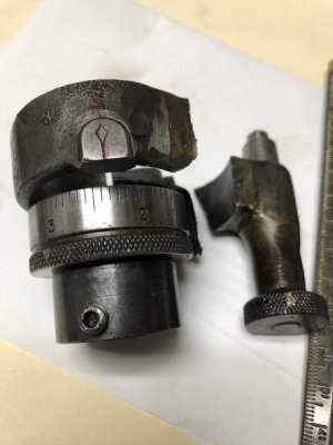
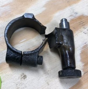
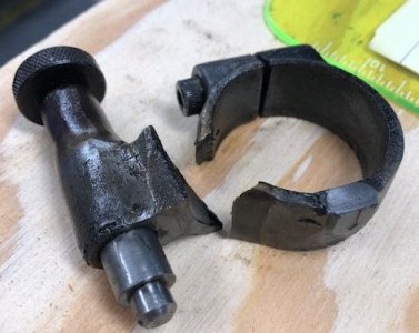
The collar locks onto the shaft to allow rotation of the shaft from one locking hole to the free hole.
I agree, the collar is a tight fit and a critical dimension.
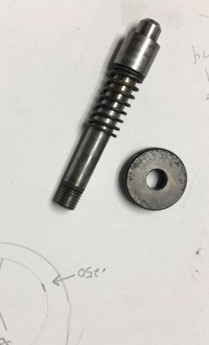
Regarding the locking pin, it doesn’t need to be anything fancy
Your drawing provides enough direction for me to go forward with this.
The A2 is the right size, I have friends with heat treat ovens.
 
The collar is .765" wide. It's a casting, the machined portion where the plunger is and the index mark is .825"
As far as I can measure, the center of the shaft to the center of the locking holes is 1.250".

ThehIMG_3256.jpgIMG_3259.jpgIMG_3266.jpgIMG_3271.jpgIMG_3274.jpg
 
Is there a piece missing that mounts the broken assembly to the RT main casting? It looks like there was some type of flang that would get bolted onto the casting that i dont see in the pictures.....could you clear this up for me please?
 
Is there a piece missing that mounts the broken assembly to the RT main casting? It looks like there was some type of flang that would get bolted onto the casting that i dont see in the pictures.....could you clear this up for me please?

If you go back to the fourth picture of the first page of this thread, this is before any un-assembly. The collar I am attempting to fabricate locks onto the shaft with the cam. The shaft is held in by a 1/4 crescent moon piece that puts pressure on a recessed portion of the shaft. It can still spin it just cant come out. (it's a two piece shaft)
I have attached a sketch of my first impressions of the part thanks to Superburban and one more pic of the pieces and how they are arranged.
I think I can face this piece of A2 to size (width) and band saw the basic shape. Layout the center hole of 1.504" which I can bore in the lathe using the 4 jaw. Drill and countersink the1.250" radius hole which is 3/8". Use a slitting saw in the mill to cut the tangs.
As this develops I'll ask for help. For a hobby guy like me, this is a challenge but I can do it.

Edit; I think i'll shorten the plunger shaft and use it- fabricate a holder for it
 

Attachments

  • 20190815100803.pdf
    17.1 KB · Views: 2
  • IMG_3277.JPG
    IMG_3277.JPG
    39.1 KB · Views: 11
  • IMG_3254 (2).JPG
    IMG_3254 (2).JPG
    80.3 KB · Views: 10
  • IMG_3255 (2).JPG
    IMG_3255 (2).JPG
    78 KB · Views: 10
  • IMG_3278.jpg
    IMG_3278.jpg
    27.6 KB · Views: 10
Last edited:
Now that I have decided to make this clamp I am thinking about the steps and sequence of ops.
1. face to size
2. bore 1.504"
3. place on RT with shaft going through hole and mark center of locking pin with transfer punch.
4. Drill locking pin hole.
5. Mill flats on both sides of tabs that hold the clamping screw.
6. Using a slitting saw to cut through one side to 1.504" hole.
7. Begin shaping the body with band saw and belt grinder

See any hole in this plan? The stock is A2 1X2"

Edit; I should move this to the projects section.
 
Back
Top