Getting reverse to work on a 120V split-phase motor with a drum switch

DoogieB

Active User
Registered
Joined
Dec 31, 2013
Messages
327
I've been using my SB 10K for awhile now with a 120v, split-phase motor. I'm at the point now that I would like to get reverse working for some metric threading but I've been completely stonewalled in having the motor switch directions correctly. This is a popular search topic, but I have yet to find the exact same motor/switch combination that I'm using. Before I waste another day in the shop, I thought I would try here for some help.

Here's the motor:

http://www.grainger.com/product/DAYTON-GP-Mtr-4K913?s_pp=false&=

And a pic of the label:

motor_1.jpg

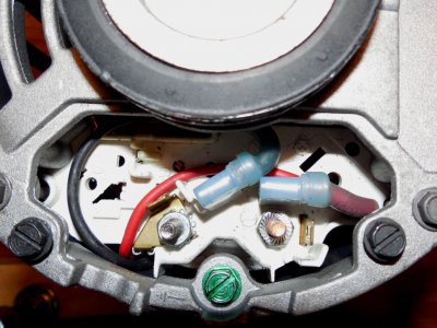
And a pic of the wiring terminals:

motor_2.jpg


From the factory, it's pretty easy to reverse the motor, just swap the black and red wires.

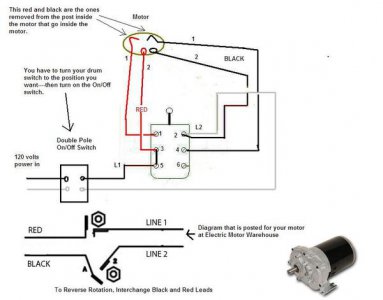
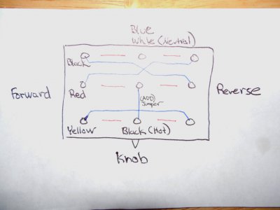
My lathe has a Cutler-Hammer drum switch. I could take a picture of it, but it will be very hard to decipher, so here's the schematic I used to wire it up.
motor_3.jpg

Each circle in the diagram is a screw. The blue lines are factory-installed jumper wires, except for the one I added in the middle. The red lines are the poles that are connected when the switch is activated, the left ones to the middle screws when forward is selected, the right ones to the middle when reverse is selected. Of course, in the middle none of the poles are connected (off). The black and white wires are 120v from the wall plug, the blue and yellow go to the main motor winding (screw lugs 1 & 4 in the motor pic above) and the red and black go to the start winding (red and black wires).

The neutral and blue wires are connected together and the black (hot) wire is switched, like a house light switch, so the main motor windings are connected the same for forward and reverse. The top two poles switch the red and black wire polarities.

When I tried the diagram as above, the motor worked and switched directions perfectly, but unfortunately the centrifugal switch seemed to be out of the circuit so the start winding was always activated, which is a very bad thing! Luckily, I noticed the motor sounded strange and was able to disconnect it long before the magic smoke came out.

Using a flashlight to look behind the panel, it seems the centrifugal switch is behind terminal 5. So I guess I need to run another wire to terminal 5 for a 5 wire setup? Then what? The right-top switch terminals are empty... Hmmm. This is harder than it should be. I feel like I'm missing something obvious.
 
Last edited:
I think I've seen that schematic before, Jim, but it's different enough from what I'm using that I couldn't make heads or tails out of it.

The good news is that the process of posting my question seemed to have focused my mind a bit on the problem at hand and I had an idea soon after. Today I got the motor strapped-down to the work bench and went to work on it with a voltage source and DVM to verify the theory. Basically terminal #5 is the centrifugal switch...

Ahhh, that was close, but I'll just edit-out that bogus information to cut down on the confusion. See next post.
 
Last edited:
Well, it was a struggle, but I got the motor working perfectly!

:victory::victory::victory::thumbsup::thumbsup:

Somehow I managed to get the start circuit backwards, but I was able to puzzle it out and now my South Bend 10K has forward and reverse.

:applause::applause:

I'll post the correct schematic with some pictures later to help out the next poor soul with this motor/switch combination, but right now I think I've earned a yummy steak off the grill and a adult beverage. Or SIX!
 
Time to get this thread updated before I forget how I did it. :))

First off, a safety notice. While this circuit isn't unsafe, it's not as safe as it could be because the neutral-line is not switched: it's always connected between the motor and the outlet with a wire nut. Now, there's a million light switches wired this way without a problem, but this could lead to trouble if the outlet is wired backwards. If that's the case, then instead of switching the hot lead you are switching the neutral and the motor will always be hot.

You can't get around this using a drum switch that only has 3 poles, like all these lathes seem to use. You can add a separate magnetic switch for the neutral. For my own use, I'm not worried, but just make sure to test the outlet first.

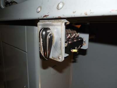
The motor is a Dayton 4K913BE. The switch is a Cutler-hammer 5441H27A.

This is what the switch looks like:

switch3.jpg

I could upload a picture of the bottom of the switch, but it's so full with wires I can't see how it will help.

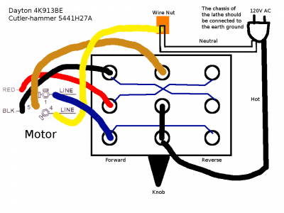
Here's a schematic.

switch.png
The dark blue lines are the factory jumpers installed in the switch. Make sure they are working. You will need to add one jumper off the hot to power the start winding as shown.

When you turn the knob, the middle terminals are connected to the terminals on the selected side.

The bottom row powers the main motor winding. It's powered the same in forward or reverse: hot to yellow and then blue to neutral.

If forward is selected, the start winding is powered by the user-added jumper from the bottom row and then it's through the red wire, through the start winding, then out the black wire and then back to terminal 5, through the centrifugal switch and then out the blue wire to neutral. When the motors reaches 75% speed, the centrifugal switch trips open to deactivate the start winding and keep the magic smoke inside the motor.

Selecting reverse reverses (surprise!) the red and black wires: hot-black-start winding-red-terminal 5-centrigual switch-blue-neutral.

This motor is not an instant-reverse motor. If you quickly turn the switch from one side to the other, it will just keep chugging away the same direction because the centrifugal switch will keep the start winding open. With a lathe with a threaded chuck, this probably isn't such a bad thing.

The wiring is actually quite logical and makes sense, it just took awhile for me to get there. Hopefully this will help someone at some point.
 
Last edited:
That's how I wired my Logan. Works fine. There's nothing wrong with not switching the meutral on a 120 circuit.

An anti-plugging relay might be helpful as it is not too hard to accidently go past stop to reverse with the result that the machine just keeps on running, possibly causing a crash or an injury.
 
Time to get this thread updated before I forget how I did it. :))

First off, a safety notice. While this circuit isn't unsafe, it's not as safe as it could be because the neutral-line is not switched: it's always connected between the motor and the outlet with a wire nut. Now, there's a million light switches wired this way without a problem, but this could lead to trouble if the outlet is wired backwards. If that's the case, then instead of switching the hot lead you are switching the neutral and the motor will always be hot.

You can't get around this using a drum switch that only has 3 poles, like all these lathes seem to use. You can add a separate magnetic switch for the neutral. For my own use, I'm not worried, but just make sure to test the outlet first.

The motor is a Dayton 4K913BE. The switch is a Cutler-hammer 5441H27A.

This is what the switch looks like:


View attachment 85826

I could upload a picture of the bottom of the switch, but it's so full with wires I can't see how it will help.

Here's a schematic.

View attachment 85825
The dark blue lines are the factory jumpers installed in the switch. Make sure they are working. You will need to add one jumper off the hot to power the start winding as shown.

When you turn the knob, the middle terminals are connected to the terminals on the selected side.

The bottom row powers the main motor winding. It's powered the same in forward or reverse: hot to yellow and then blue to neutral.

If forward is selected, the start winding is powered by the user-added jumper from the bottom row and then it's through the red wire, through the start winding, then out the black wire and then back to terminal 5, through the centrifugal switch and then out the blue wire to neutral. When the motors reaches 75% speed, the centrifugal switch trips open to deactivate the start winding and keep the magic smoke inside the motor.

Selecting reverse reverses (surprise!) the red and black wires: hot-black-start winding-red-terminal 5-centrigual switch-blue-neutral.

This motor is not an instant-reverse motor. If you quickly turn the switch from one side to the other, it will just keep chugging away the same direction because the centrifugal switch will keep the start winding open. With a lathe with a threaded chuck, this probably isn't such a bad thing.

The wiring is actually quite logical and makes sense, it just took awhile for me to get there. Hopefully this will help someone at some point.

Boy, I really needed this. Thank you!
 
Back
Top