Gilbert Erector set 1913 motor

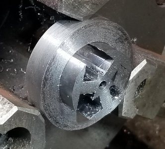
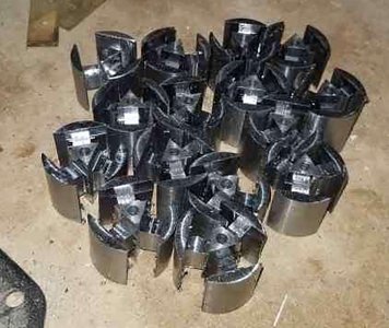
Also did some tooling/fixturing for dressing the ends of the armatures. The armatures had a secondary op to cut down the three legs so the wrapped wire doesn't stick out past the ends of the part. Also, the tops of the "T"s are turned down around 0.030" so the center area is ~1.030" long and the tops of the "T"s are ~0.970". That's so the center area can bear up against the armature bracket without the top of the "T" potentially hitting the bracket.

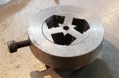
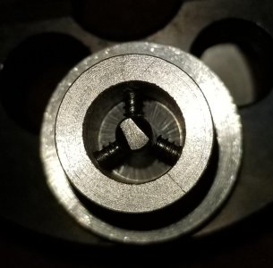
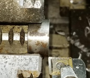
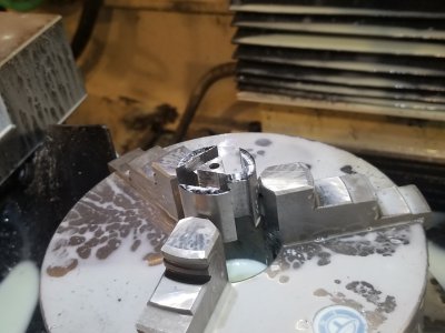
Hman had a good idea using the 4th axis on the flat. Instead of mounting the 4th, I mounted the 3-jaw chuck. Plan was to orient the parts off one of the chuck jaws, so it was trammed in before clamping the chuck to the table.


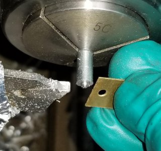
Swept a chuck jaw for angular orientation.
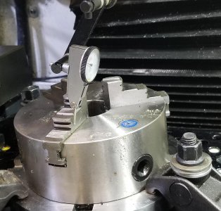
20201227_155352.jpg

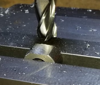
Used the Tormach's built in probing "find the center of a round boss" routine to establish X and Y.
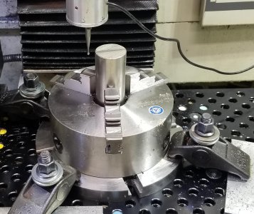
20201227_154127.jpg


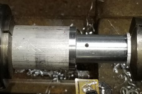
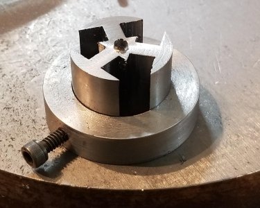
For those who don't do any CNC work, it's a WONDERFUL way to do repetitive operations. In this case, the routine would be cutting a triangle to depth on the end of the armatures. After that, it ran a circle across the top of the "T"s to relieve that area from hitting the armature bracket while the motor is running. I used the probe to find the center of the chuck, and planned on using it to find the surface of the armature to establish Z=ZERO for the proper depth of cut. Each armature needed to be machined on both surfaces, plus there were 20 or so parts to machine. Figured the best way to get away with setting the height just once, plus be able to angularly orient the parts in the 3-jaw was to make a bushing/depth stop.

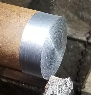
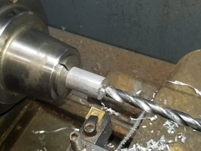
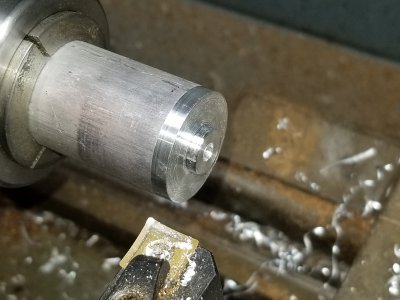
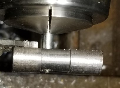
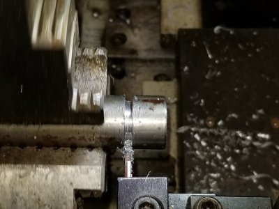
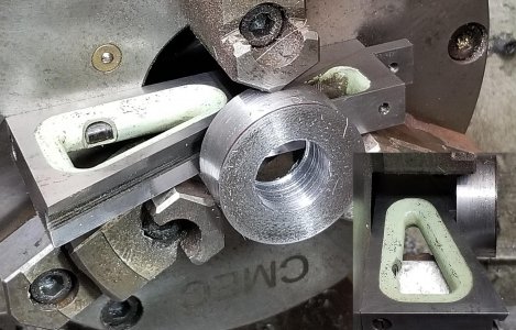
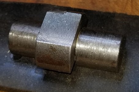
Started with a 2" round of mystery steel. Faced, and cleaned up the OD.
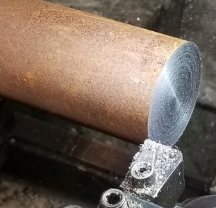
20201226_162421.jpg
20201226_162814.jpg

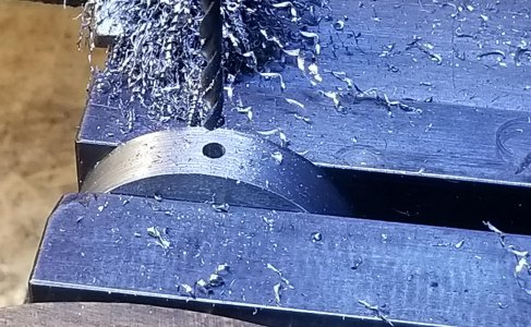
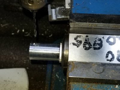
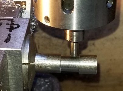
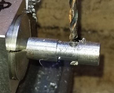
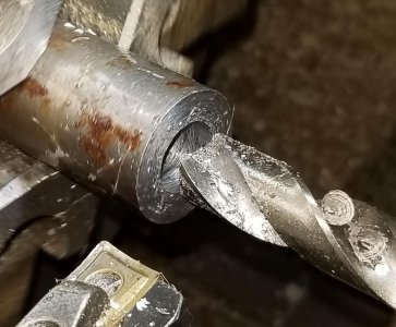
Band sawed off a length and drilled a center clearance hole.
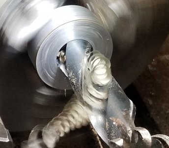
20201226_164908.jpg

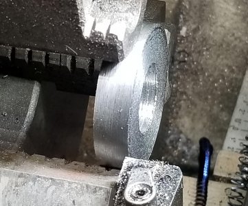
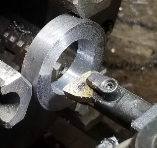
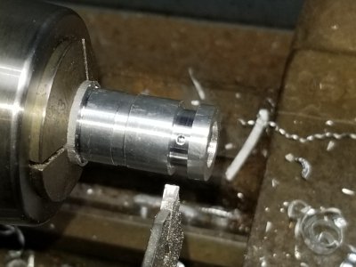
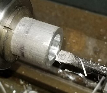
I used a planer gauge against the chuck surface to set the bushing flat. Then faced to height and bored the center so an armature was a slip fit.
20201226_165720.jpg
20201226_170349.jpg
20201227_143707.jpg
20201227_143852.jpg

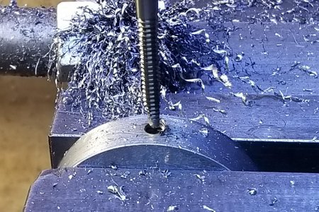
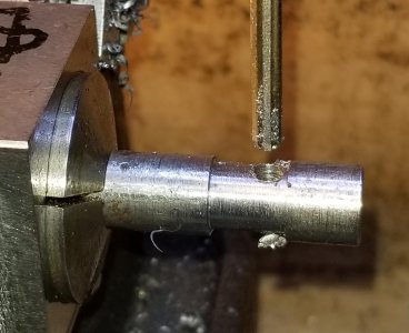
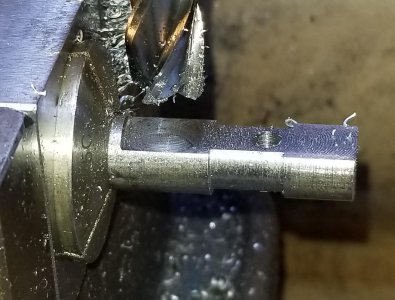
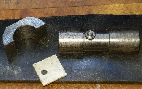
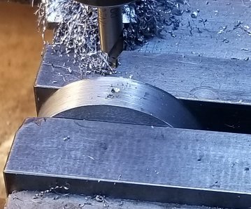
Then on to the Bridgeport to center drill, tap drill and tap a 10-24 clamp screw hole
20201227_144107.jpg
20201227_153055.jpg
20201227_153828.jpg


In use, I'd tap the armature surface to be cut into the bushing and tighten the cap screw. That set the surface of the armature flush with the surface of the bushing.
20201227_155602.jpg
20201227_160951.jpg

Couple of nice things about this set up. The bushing is a known thickness, so the armature surface is also. I probed the surface with an armature in the 3-jaw to set Z. As long as I kept chips off my vise deck (my reference surface) and chuck jaws, setting subsequent parts should be spot-on in Z (saves continually probing the height).

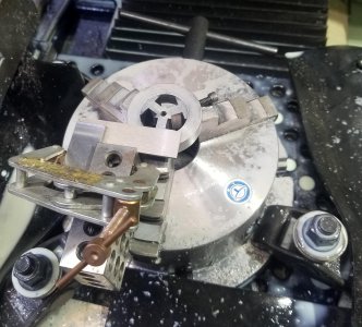
The other nice feature is the armature/bushing could be clocked before tightening the 3-jaw to get the armature angularly oriented. The bushing set on top of the vise jaws so the part didn't fall into the chuck. I clamped a square to a 1-2-3 block for an alignment fixture. Set the 1-2-3 block against the chuck jaw and rotated the armature/bushing until the "T" was flat to the square, then tightened the chuck.

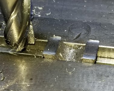
Pull the bushing, hit "CYCLE START" and walk away. I LOVE this CNC for this type of work. The routine cut the legs of the "T"'s (triangular path) and did a 0.035" pass on the top of the "T"s. Made relatively quick work of the stack of armatures.
20201228_125956a.jpg

20201228_125956.jpg

20201230_163859.jpg


Thanks for looking, Bruce
 
Wonderfully creative! I can't help wondering what the old A C Gilbert folks (or anybody from that era, for that matter) would have thought if they'd been able to catch a glimpse of CNC tools. And too bad we don't have a "time machine" video viewer with which to glimpse the future. Meanwhile, Happy New Year to all!
 
Get ready for a long-winded update on the 1913 Erector set motor project. I originally estimated the world-wide demand at around 20 motors. I made up 30 of them just in case. I’ve sold close to 25 of them to date with no advertising other than offering a few on eBay in two separate auctions. I brought a number of them to the Erector set collecting club’s national show and did well there. Well, time to fire up the presses and make some more. . .

One of the things I like about this hobby is trying to figure out better and quicker ways to do things. I didn’t take any pictures of it, but I’ve changed from a die grinder to a needle scaler to rough up the field magnet and armature. This chopped A TON of time out of the process; at least an hour of total time.

Another of the components that takes quite a bit of time is the commutator/motor switch. I originally made them by gluing a brass tube over an oak dowel (bottom of the first page of this string). I think the details are on the first page of this string. My original method required work on the mill, lathe and drill press. Then bench work to run tiny #2 screws into an oak dowel.

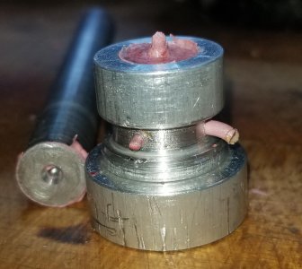
I’ve seen these motors with commutators/motor switches with the body made from an oak dowel or a reddish fiber material. My improvement for the next batch was to make a mold to cast the bodies of the commutator/motor switch. The mold would have the center axle hole cast in along with the threaded holes for the contact screws. I’d also make a die set to form the contacts.

First the mold. Plan was to use a product called “Pig Putty” for the mold material. It’s an epoxy putty that sets up in 3-5 minutes and gets hard in about 4 hours. The molds were made from aluminum.

The original part was about 0.5” long and cylindrical at a diameter of ~0.470”. One end had a taper on it which acted like a spacer washer. The contacts were short of the end of the base so they didn’t short out on a supporting bracket.

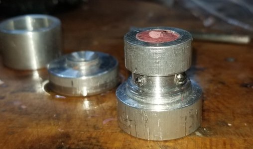
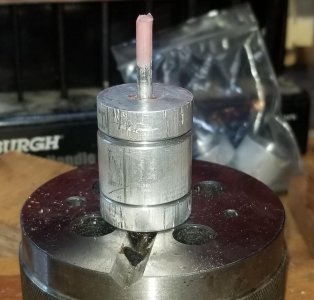
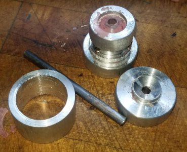
My mold design consisted of 5 pieces plus screws/nail. The screws/nail would be inserted into the main core so the threads/nail hole would be cast in. The main core was a ¾” OD round with the center drilled out/bored to 0.470”. Holes for the screws/nail (nail was the motor switch handle) were drilled through the core for inserting the screws/nail in place. Two end caps were made to seal off the ends of the mold: one with a square shoulder and the other with a tapered end. A bushing from 1” aluminum slips over the main core and acts as a retainer so the screws don’t squirt out of the mold as the epoxy is packed. The end caps also have a centered hole for the axle to pass through. The axle also acts as a plunger when inserted to pack the mold.


Mold body for the cylinder. Drilled and bored the ID to size.
20210725_145131.jpg

On to the mill in a hex-collet block to drill clearance holes for the #2 screws that'll be inserted into the mold
20210725_151516.jpg

Cut a groove in the mold so the heads of the screws were just sub-flush to the OD of the mold
20210725_161818.jpg

Turning one of the mold end caps. These were center drilled and drilled with a 5/32" through hole for the armature axle.
20210725_154042.jpg

Turned the shoulder diameter to size and verified with the mold core
20210725_154059.jpg

Set the center axle in place and progressively ground down the tips of #2 screws until they just cleared the axle. Idea is the putty will harden around the screws. After set-up, back out the screws leaving the threaded holes behind.
20210725_162838.jpg

Boring a sleeve to fit over the mold core. This bushing slips over the mold core after the screws are inserted and keep the screws from popping out as the mold is pressurized.
20210725_164532.jpg

Checking fit of the retaining bushing with the mold core
20210725_164555.jpg

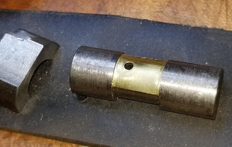
Final mold pieces (retaining bushing, mold core, end cap with a tapered end, end cap with a flat end.
20210729_155959.jpg


The photos of the mold construction were actually my prototype. I ended up making a couple of revisions to the main core and bushing to speed up mold making. I ended up making 3 molds for the commutator core and 3 more for the switch.

The original parts were a reddish insulating material I believe called “fish paper”. Pig Putty has a bluish-gray tint which I planned on painting after the fact with some red brick acrylic paint. Instead, a couple of drops of the paint were mixed into the putty as it was kneaded.

Molding goes pretty smoothly. Mix the epoxy, stick the rough cylinder in the mold core. Set the square-shouldered mold cap in place and press down on the epoxy with a pin slightly under 0.470”. This initially packs the epoxy into the mold; I’d apply pressure until the putty was squirting out of the core screw holes. Then set the screws/nail in place and drop the screw retaining bushing over top. Repeat mold packing with the pin/ram. Set the tapered end cap in place and insert the axle. Tap down on the axle with a brass hammer until the mold starts to spread, then squeeze the mold tight again; putty would squirt out the opposite end cap from the axle. Repeat the axle tapping, mold squeezing until the axle entered the opposite cap. The axle was driven through the opposite end cap and clamped together with a couple of wooden blocks and a C-clamp.


Cut off a chunk of Pig Putty and mix in a few drops of brick red acrylic paint
20210821_100735.jpg

Put the putty in the mold core, set the flat end cap in place and push down on the putty with a pin/ram to pack out the mold. I figured the air was gone when there's putty squirting out of the screw holes.
20210821_100932.jpg

Insert the screws/nail (for the switch), set the retaining bushing over the mold core to keep from squirting the screws out and pack the mold again. This would squeeze the epoxy putty tight around the screws.
20210821_101028.jpg

Set the tapered end cap in place, squeeze the mold tight, then drive the center axle through the mold. Note the putty driven out through the end cap.
20210821_101825.jpg


Demolding after 4 hours was just a reverse of the operation. I used LPS 1 lubricant as a mold release on the mold pieces prior to inserting the epoxy.


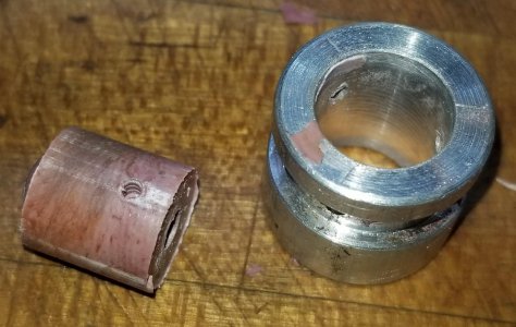
Demolding started with driving the axle out with a brass hammer. Then twist off an end cap, pull the retaining bushing and unscrew the #2 screws (and/or pull the nail). Tap out the epoxy casting with a pin.
20210821_100036.jpg

20210821_100322.jpg


I'll go on to a part 2 for the contact die and final assembly. Thanks for looking, Bruce
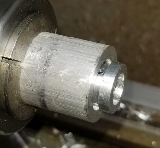
 
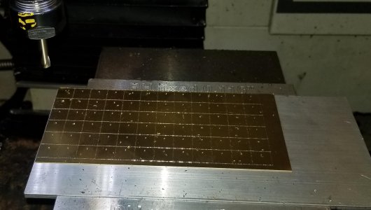
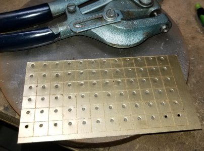
The contacts were done on my Tormach 1100. The base stock was 0.015” brass. The CNC routine used a diamond engraver and spotting drill to rough out the parts. The screw holes were punched with a Roper Whitney #5 hand punch. In retrospect, I’ll try drilling the holes on the mill with the next batch. I typically only punch holes in sheet metal, but maybe the brass would drill okay. Regardless, using the CNC to layout the contacts saves a ton of time over hand scribing.


Layout work takes time. I used the CNC to scribe the contacts and center drill the screw hole which saved a lot of time.
20210808_170544.jpg

Punched the screw holes with a Roper Whitney #5 Junior hand punch. For the next batch, I'll try drilling the holes with the Tormach.
20210810_164204.jpg

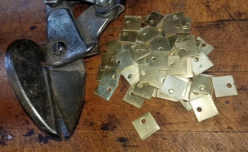
Cut the contacts into blanks ready for forming with a Tennsmith stomp shear and a hand shear.
20210814_113000.jpg


The die set for forming the curve in the contacts was made from CRS. I figured the brass was soft enough to not need O-1. As you can see from the lathe/mill work, the die set was pretty simple so a second one from O-1 wouldn’t set me back too far.

The design here was a lower die mandrel at the ID of the contact and an upper die bored to the OD. The lower die was made from 5/8” stock with a center area turned down to 0.470” at the overall length of the contact plus a few thousandths. This gave a recessed area for the contact to set in before it was formed into an arc by the upper die. Otherwise, I was afraid the contact could rotate resulting in the edges not being parallel to the center of the commutator axle. I also machined in a pin in the lower die that the contact blank sets on. This keeps the contact from slipping off the lower die.


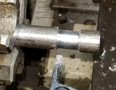
Turned the center of the round to diameter and a few thousandths longer than the contact. Idea is to set the contact on this surface and hit it with a "U" shaped upper die to form an arc in the brass.
20210801_120503.jpg

Found the edge of the step
20210801_121332.jpg

Drilled an under-sized hole
20210801_121724.jpg

Over-size reamer for a loose locating pin
20210801_121927.jpg

Milled a flat on the bottom of the die so it wouldn't roll off my bench!
20210801_122522.jpg

Retaining pin for the contact. Left a nub that fits snuggly into the contact hole
20210801_123421.jpg

Set the lower die on the pin so the nub just stuck out above the surface and parted.
20210801_123543.jpg


The upper die was made from a piece of CRS. Center hole drilled and bored to 0.500". Parted and faced the upper die to length. The "O" was milled into a "U" at the Bridgeport.


Drilled/bored a length of CRS to 0.500".
20210801_111918.jpg

Parted to a rough length. The contacts are 0.45" tall, the upper die is about 0.44" for a little clearance at the top/bottom.
20210801_112401.jpg
20210801_112950.jpg

Milled a flat for a hammer target
20210801_113836.jpg

Flipped the "donut" and made it into a "U".
20210801_114807.jpg

When mashing the parts, the lower die is set on a sheet of rubber. The contact is set in place, upper die held in place, then tapped a couple of times with a 16 oz. ball peen hammer. The rubber allows the retaining pin to retract some so it doesn’t get peened over by the upper die. Then the lower die without the pin is set on the hard-surface bench and the contact is struck again with the upper die.


Finished die set. Brass contact sets on the pin. The lower die relieved area is a few thousandths shorter than the contact.
20210801_124727.jpg

Set the upper die on top of the contact and give it a couple of taps with a 16 oz. hammer. The die was set on rubber so the retaining pin would sink down and not peen over or dent the upper die.
20210801_124903.jpg

The contacts were tight to the die even with rubber on the bottom. But for belt and suspenders, I'd pull the pin, set the die on the bench and give it another hit.
20210801_124912.jpg

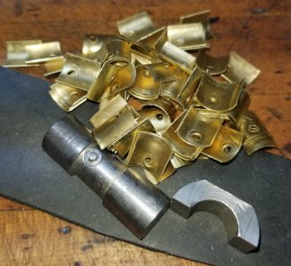
Lotsa contact, actually goes pretty quickly.
20210814_123519.jpg


Hit the photo limit, so on to part 3. . .

Thanks for looking, Bruce
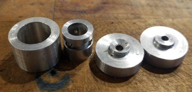
 
Assemble was done with the aid of a bench block. For the commutator, the axle was glued in place by the factory. I do the same using Gorilla glue. Mark the axle where it’ll be in the commutator molding, knock in a couple of dents with a hammer and glue it in place.

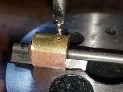
The commutator/switch base are set on a bench block, apply a dab of Gorilla glue, set a contact in place and run in a #2 screw. I didn’t show it, but I wrapped the cylinders with a piece of wire twisted tightly to hold the contacts to the molded base as the glue dried.


For the commutators with an axle, peened the center and Gorilla glued it in place. The photo doesn't show it, but I slip a molded base on the opposite end so the assembly sets flat on my bench block. Put a dab of glue in place, set the contact and run a #2 screw into the molded hole.
20210821_104313.jpg

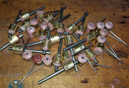
Molding the center cylinders and stamping the contact saved a ton of time on this batch.
20210822_113016.jpg

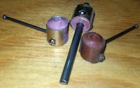
My reproductions on the left and center, original motor switch on the right. My color is actually closer than what the photo shows, it's really hard to tell mine from the original part.
20210823_161931.jpg


Overall, molding the parts cut out more than half the time to make the commutators and motor switches. Pretty happy how they came out.

Thanks for looking, Bruce
 
Fascinating stuff. It always drove me crazy doing a pile of parts. So I would dream of ways if I was going to do it how I would do it. Doing a million small pieces is the perfect time to devote to that. Good job, lots of great ideas.
 
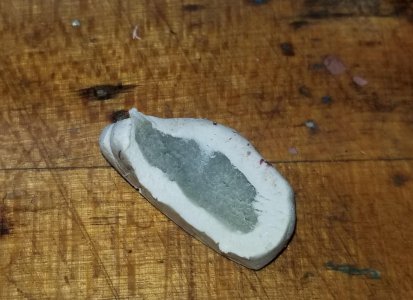
Bruce, that's truly a fantastic build! I especially liked the last photo in part 1 - the completed casting. The slightly irregular coloration really gives it character!
 
Looks good but silly question.

Why are you removing the shaft to latter glue it in?

Seems like you could kiss it on the grinder where the casting goes to give the. Epoxy something to grip and cast it as done.

Sent from my SM-G781V using Tapatalk
 
Why are you removing the shaft to latter glue it in?

Seems like you could kiss it on the grinder where the casting goes to give the. Epoxy something to grip and cast it as done.
Good thought for the commutator/armature. The motor switch would still need the axle driven out as a screw is run into the wooden base for a pivot.

For the armature, I could drill out a piece of aluminum for a drive ram to demold the part. The ram would need to freely slip over the axle and be turned to under 0.47" on the OD to clear the mold. Might be an improvement for the next batch. Thanks for the idea!

Bruce
 
All about reducing steps and saving materials.

Great work by the way, very clever.
Sent from my SM-G781V using Tapatalk
 
Back
Top