- Joined
- Nov 23, 2014
- Messages
- 2,606
Yup, yet another Erector set reproduction part. This one is part number “CI” brass segment. First the obligatory history lesson.
Gilbert listed the part in the 1924-1933 manuals, but only included it in the 1924 – 1926 No. 8 and No. 10 sets (two largest sets). Curiously, the part(s) are not shown in use in any of the illustrated models. The only place I’ve seen it used was in the swivel until of an Airplane set sold from 1928 – 1932. Oh, really good design here. In use, little “Johnnie” nailed the swivel unit to the ceiling and hung the steel airplane model from the power cord running down to the motor. I’ll have to Google when OSHA came into existence . . .
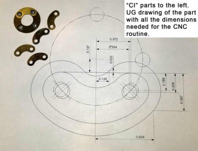
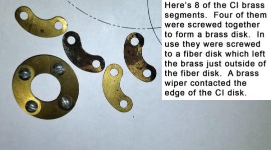
The parts were made from 0.015” thick brass and were roughly 1.1” long by 0.520” tall. Four of them could be set in a ring to form a brass disk with an OD of 1 3/8”. Hole spacing across the disk is 1”.
Lots of ways to attack this part. My assumption is they were originally stamped in one shot. I have a CNC Bridgeport in my shop which would make life pretty easy cutting a punch and die, but went a more manual route instead. It boils down to how many are needed. I’m guessing that the world-wide market is for 50 parts over the next 5 years, so shied away from a punch/die. Plan instead was to cut them on the CNC Bridgeport.
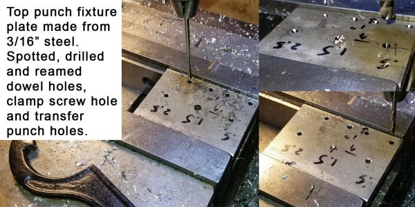
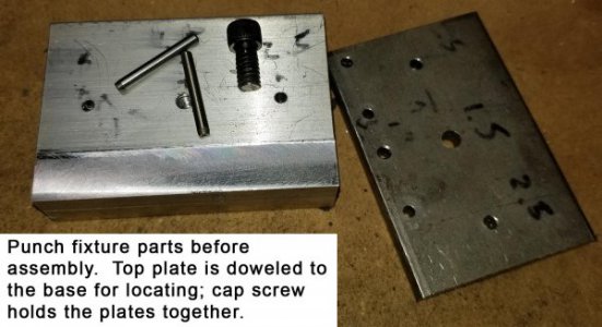
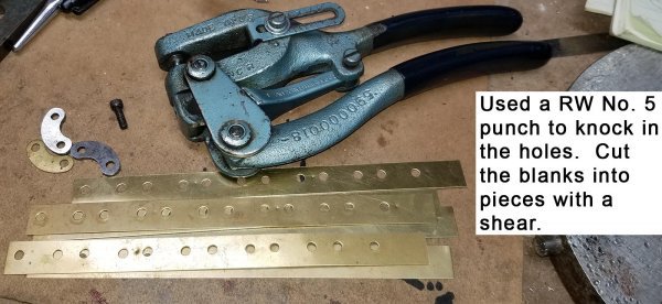
First step was to make the blanks. The holes are 11/64” diameter spaced 0.707” apart. I could have made a dual punch/die to knock two holes at once, but again went a more manual route. Instead, made a fixture from aluminum and steel to transfer punch the holes for subsequent punching with a Roper Whitney No. 5 hand punch.
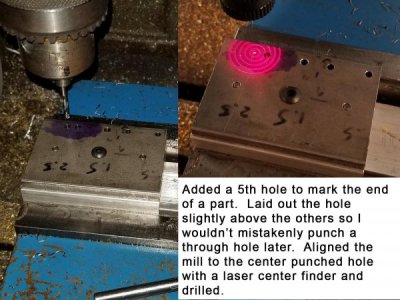
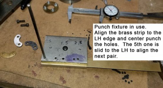
The base has a rabbet milled on an edge to locate a strip of brass. Top plate is 3/16” thick steel. The base and top guide plate were drilled and doweled together for alignment. The top plate had holes drilled and reamed for an 1/8” transfer punch to locate the two holes in a couple of parts. The LH edge of the fixture and first hole were set so in use the edge of the brass strip is set to the LH edge of the fixture so there’s just a little extra material on the blank for trimming to size. An afterthought was to add a fifth hole to mark the space between another pair of parts. This let me mark the end of the 2nd part so the blank strip could be slid into place for punching the next pair of parts.
The blanks are 5/8” wide which was cut on my Tennsmith shear. Transfer punching goes pretty quickly, set the brass strip in the fixture, flush the left edge of the brass strip with the left edge of the fixture, punch 5 marks, then slide the strip down so the 5th punch mark is lined up with the LH edge of the fixture and repeat. Punching was done with a Roper Whitney No. 5 Junior punch.
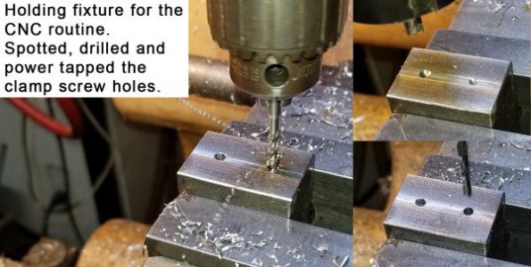
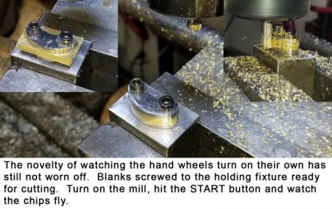
Made a quick holding fixture for the blanks on the BP from a block of steel. Spacing is 0.707” between the holes. Spotted, tap drilled and power tapped two 8-32 holes for clamping screws.
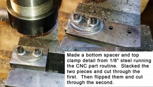
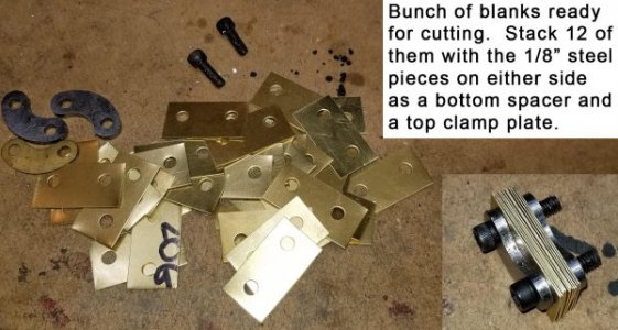
It’s mighty convenient to have a wife who’s a Unigraphics designer! My wife Tracy drew up the part in UG and gave me all of the coordinates for the CNC programming. I dry ran the program in space which looked good. Marked the 0.707” holes using the punch fixture into a pair of 1/8” steel plates for spacer/clamp blocks. My plan was to make a couple of 1/8” steel parts which would be used as a spacer on the bottom of a stack of brass blanks so the cutter didn’t hit the top of the holding fixture, and a second one on top of the stack of blanks for clamping.
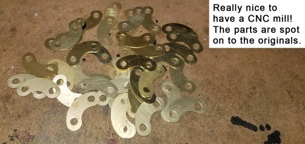
Ran the routine at 10 IPM which ended up taking about 30 seconds to run the job. I could comfortably stack up 12 brass blanks and do the cutting in one pass. The parts look great. They usually sell for $2-$4 each, so not a big money maker but it adds to my “portfolio” of wares for sale at shows.
Thanks for looking,
Bruce


