- Joined
- Nov 23, 2014
- Messages
- 2,606
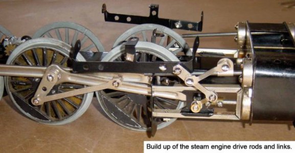
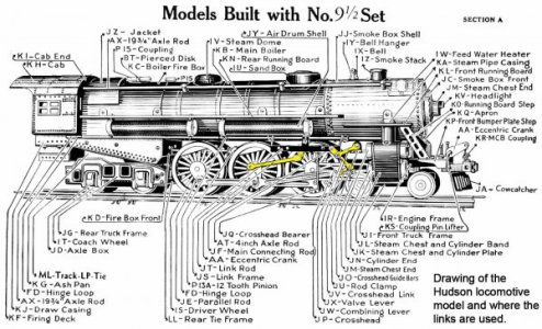
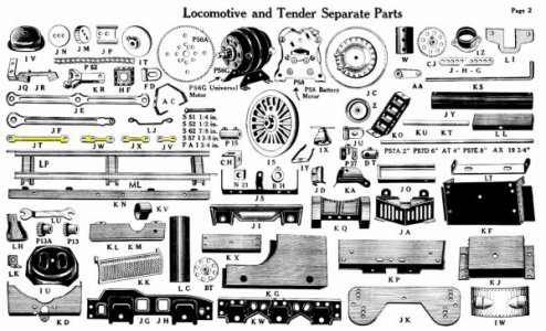
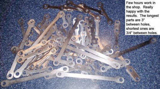
Well, here’s another string detailing a set of Erector set parts being reproduced in my shop. Four different parts are combined in one post here as they are very similar. Part numbers are Gilbert Erector set parts JT, JV, JW and JX. They are sheet metal (~0.045” thick stock) links used in the construction of the iconic 1931 – 1937 Gilbert Erector Hudson Locomotive model.
There are some pictures attached of the model pictorial (locomotive is about 28” long) and the build up of the steam engine drive rods and links.
I’ve made these before by hand trimming and filing, but that was for 1 or 2 at a time. I picked up a Bridgeport CNC mill this past fall and been having a ball reassessing how to make things. No need to hand trim a pattern and file when you’ve got a BP that can do all of the tedious work for you!
My BP has a 30+ year old Anilam Crusader II controller which works well, but the communication feature through the RS-232 port does not work. That means it can only be programmed directly from the controller’s keypad; routines cannot be saved to a remote computer for reloading later. I write the routines by hand and key them in, keep a file folder with the final routines for reloading if I run the job again. Yeah, a bit tedious, but better than nothing.
Started by laying the parts on our flat-bed scanner and snapped an image of each part. Brought the scans into a free CAD/CAM program called Techne CADCAM. Traced the parts in the CAD program, then dropped some ¼” circles in key places (tangent points of transitions of the parts’ perimeter) to represent a ¼” end mill. With the coordinates in hand, wrote the CNC routines which are about 35 steps long. Again, will be a bit cumbersome to have to manually input them if I make another run of the parts a year from now, but better than manually cutting, trimming and filing the parts.
The Anilam controller has cutter compensation capability. This feature allows the routine to run at an offset to the finished shape. In practice, the CNC routine can be repeated, stepping closer to the final shape on each pass. My controller is just 2-axis, so I could run the finished shape and keep stepping down in Z to the bottom of the stack of blanks. Or, start at full depth but peck away on the sides by stepping closer to the final pattern on each pass. I did the parts in 3 passes which freed me up to do other things while the mill was running.
My plan was to cut blanks from 0.048” 304 stainless steel. The original Erector set parts were made from 1008 or similar steel, then nickel plated. I’ve got a nickel plating tank courtesy of Caswell Plating, but frankly find it easier to go with the stainless steel. 304 in a No. 4 finish looks very close to nickel plated steel.
OK, now on to the blanks. The hole spacing varies on each of the parts. Many ways to mark the parts, could manually layout each part with Dykem and a caliper/height gauge. Or, print a paper template, glue it on the stock and center punch/punch the holes. Also thought about making a fixture to transfer punch hole locations that would be punched later. I hand laid out some prototypes and punched them by hand with a Roper Whitney XX punch. Could see that the 0.048” 304 stainless was going to trash the 11/64” punch after only a few hits. So, ended up going with a drill jig.
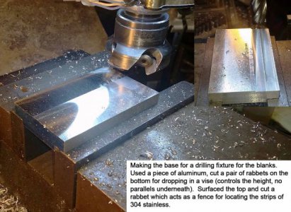
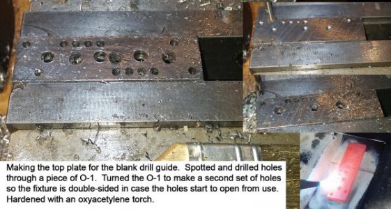
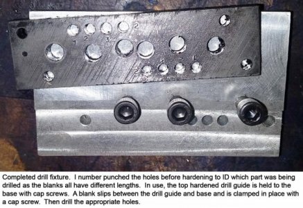
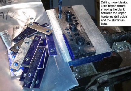
The drill jig is made from a top guide of O-1 tool steel and a base of aluminum. The base has a rabbet cut into it for a back stop for locating the strips of steel. The rabbet is a little shallower than the part thickness so when the top O-1 drill guide is clamped in place the blank is held securely. The O-1 drill guide is located with set screws, tight clearance holes on the top plate, tapped holes in the base. I made the O-1 top plate double-ended so if one side starts to wear, it can be flipped 180 deg. for a second set of holes. The O-1 was hardened with an oxyacetylene torch and was not tempered.
I used a bench shear for cutting the strips of 304 stainless. My Tennsmith is rated for a 36” piece of 0.050” stainless, parts were being made from a 12” piece of 0.048”, but it was a little closer to capacity than I’d like to stomp on. The bench shear is rated for 3/16” steel, so figured stainless less than a third that thickness would be fine (it was).
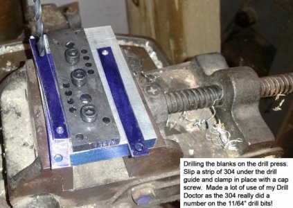
The drill jig was held in a vise on the drill press. Loaded a strip of 304 and drilled away. The 4 different strips use the same end hole, but vary on the other(s). I batch drilled a number of the same size at a time, so marked the appropriate hole with a Sharpie to aid in hitting the right hole.
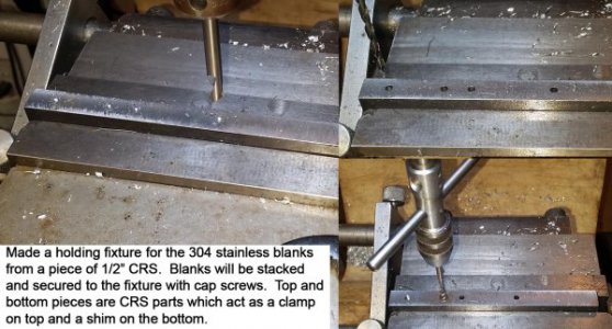
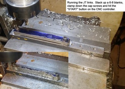
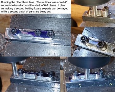
Made a simple holding fixture on the Bridgeport for securing the blanks from a piece of ½” thick CRS. Ran the CNC routine for each part with a CRS piece on the top and bottom of the stack of blanks.
On to making the parts. Ran 8-32 screws through a CRS part which served as a clamp plate on top of a stack of 304 stainless blanks. Finished off the stack with a 2nd CRS spacer to shim the stack off the holding fixture so the end mill didn’t contact it. I ran the job with a ¼” 2-flute end mill at a feed rate of 8 inches per minute. The routines took between 35 to 55 seconds to travel the path. Much nicer than the hand nibbling and filing method. Plus, the parts are spot on every time.
Thanks for looking
Bruce


