Grinding Spindle R8 taper on machine. Same for any Bridgeport styled machine.

Tim9

H-M Supporter - Sustaining Member
H-M Platinum Supporter
Joined
Oct 11, 2015
Messages
1,197
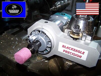
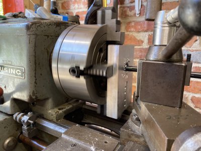
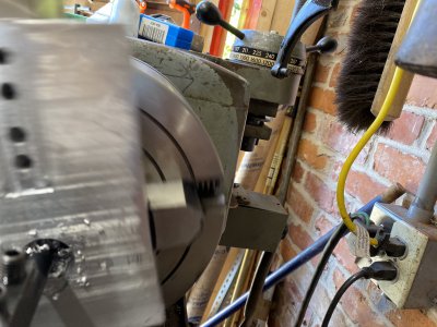
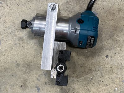
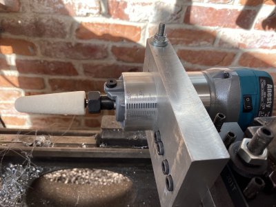
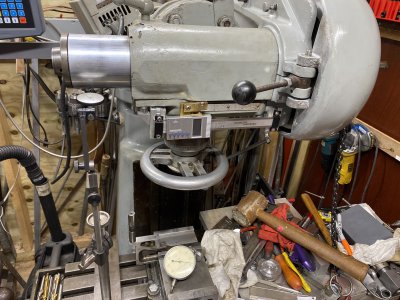
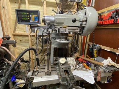
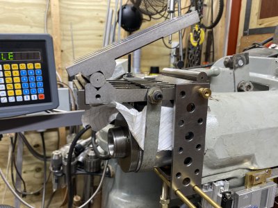
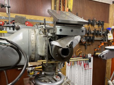
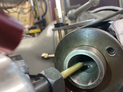
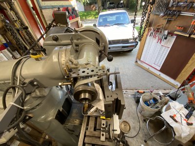
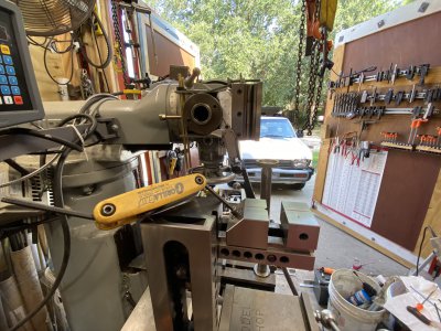
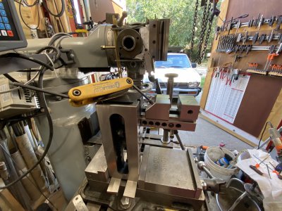
I’m going to document the recently completed Re-Grinding of my spindle on my Millrite MV1. And as a side note, this is same process which would be done on any Bridgeport turret styled mill.

I replaced my spindle bearings about a month back. The mill was never quite right since the day I purchased it. I only paid 800.00 for it, but it’s always been a bit out. Personally I think it was dropped at some point.

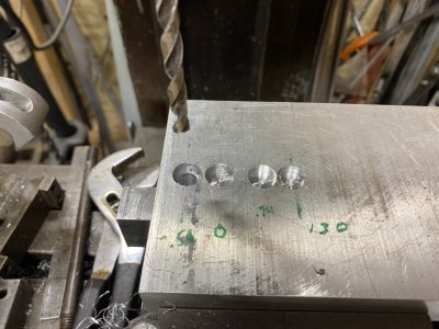
Anyway the bearings were a little noisy and the spindle was flopping around....in and out as I would drill a hole. After I pulled it apart to replace the bearings I ran into trouble with my housing and I patched that up, but there wasn’t any way to really find the high spots of the bearings to match up with the spindle since someone already replaced the precision bearings with off the shelf standard bearings.

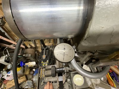
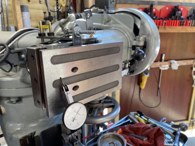
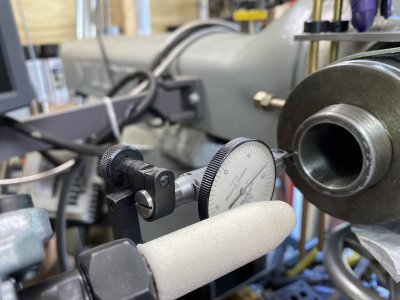
Long story short, my milling machine was always out.... between 0.0035 and 0.0055 . It was really out of specs. I thought changing the bearings would fix it, but no luck. FWIW, I went back with precision bearings but no luck on fixing my out of specs.

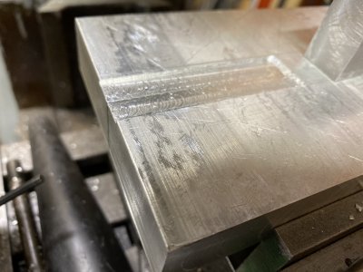
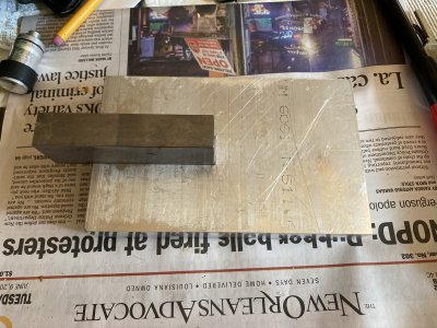
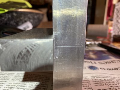
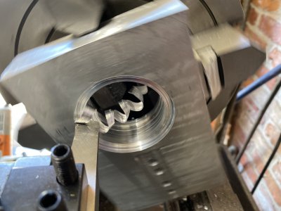
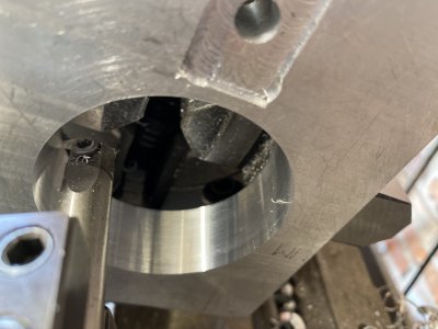
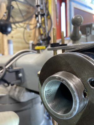
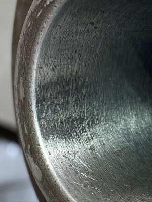
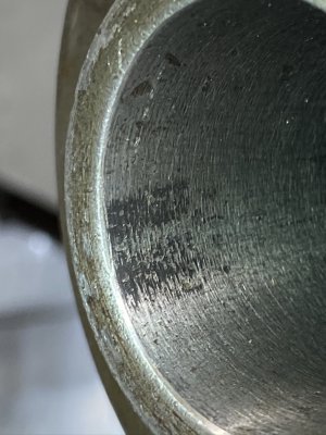
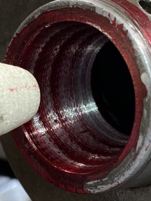
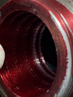
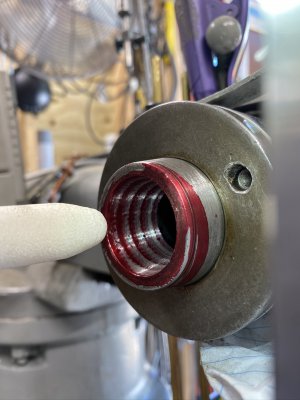
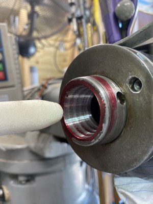
I’ll show some pics of the taper beforehand and you can see it looks like it’s was rough ground once before since it’s surely didn’t look smooth for a milling machine taper.

Anyway it came out pretty good. I’m coming up with one thousandth using a 1/8 collet and 3/4 of a thousandth using a 3/8” collet. In both cases I used a carbide drill round blank.....so I’m guessing that’s as good as I can expect out of Shars economy collets.
 
Last edited:
First thing I had to do was build a grinder. I picked up a cheap copy of the Makita RT0701C router which accepts 1/4” die grinder shanks. The 1/8” Dremel just isn’t up to the task in my opinion. Just not ridgid enough.
I then copied this set up I saw on EBay. It’s a nice set up, but I wanted the additional capability of being able to mount my grinder in a vise.


So I used some 1” thick aluminum plate. And mounted it in my 4” chuck. Cut a hole...then a slice on one end with the band saw and a bolt to allow clamping around the router housing. Then I mounted a piece of 3/4” steel plate which will allow mounting in a BXA tool holder or the vise in this case.
 

Attachments

  • 44AEEA44-0DBD-489A-A72A-1B56EBDECFF7.jpeg
    44AEEA44-0DBD-489A-A72A-1B56EBDECFF7.jpeg
    575.6 KB · Views: 44
  • EDEAED11-1A3C-4AF8-B1CA-E2984296F2F1.jpeg
    EDEAED11-1A3C-4AF8-B1CA-E2984296F2F1.jpeg
    723.8 KB · Views: 42
  • 35DC1F20-734A-4E68-98F7-186C1F2B0E00.jpeg
    35DC1F20-734A-4E68-98F7-186C1F2B0E00.jpeg
    821 KB · Views: 34
  • 3FDD566F-69F9-47C8-BC7E-EDBF604E3199.jpeg
    3FDD566F-69F9-47C8-BC7E-EDBF604E3199.jpeg
    851 KB · Views: 32
  • 92B42798-3D6A-46D6-AE43-E9CFA92C19EF.jpeg
    92B42798-3D6A-46D6-AE43-E9CFA92C19EF.jpeg
    549.3 KB · Views: 33
  • C5FBE8D8-91D9-4DCD-AF73-F520FB5CBEF7.jpeg
    C5FBE8D8-91D9-4DCD-AF73-F520FB5CBEF7.jpeg
    662.6 KB · Views: 35
  • 94BC7904-79F1-4E24-B49A-ACDBB07580BA.jpeg
    94BC7904-79F1-4E24-B49A-ACDBB07580BA.jpeg
    649.1 KB · Views: 32
  • 9BDC19EA-A1A1-4D11-9E29-66E47A7ADF1C.jpeg
    9BDC19EA-A1A1-4D11-9E29-66E47A7ADF1C.jpeg
    463.6 KB · Views: 33
  • 44923A4A-7B22-4011-BB0C-4BAD5DD873D9.jpeg
    44923A4A-7B22-4011-BB0C-4BAD5DD873D9.jpeg
    418.3 KB · Views: 36
  • 5423AC67-1877-49ED-8F70-C4D01CEDC7E3.jpeg
    5423AC67-1877-49ED-8F70-C4D01CEDC7E3.jpeg
    568.7 KB · Views: 39
  • 8440B857-11F9-4A29-A8AB-CC13D26C2A10.jpeg
    8440B857-11F9-4A29-A8AB-CC13D26C2A10.jpeg
    777.4 KB · Views: 40
I mounted my grinder on the lathe and then put a diamond tipped stone dresser in a drill chuck mounted in the tailstock. Dressed a couple of grinding stones. Now for getting the mill set up for the grind. The grinder is complete and ready.

fwiw...the white stone was dressed so it was similarly shaped like the bottom one. It was not cone shaped when finished. I just didn’t take a picture of it....so all I have is an earlier pic
 

Attachments

  • FD0020E2-6F66-4A75-B4CB-F77400AE48D2.jpeg
    FD0020E2-6F66-4A75-B4CB-F77400AE48D2.jpeg
    568.7 KB · Views: 39
  • 11AD2D1E-A55C-40F5-809B-F6DDD247DFFB.jpeg
    11AD2D1E-A55C-40F5-809B-F6DDD247DFFB.jpeg
    920 KB · Views: 46
Last edited:
There are two schools of thought on this. You can tilt your mill head the necessary angle and use your mill Z axis....ie the knee to move the grinder in and out for the grinding of the spindle taper. My problem with this is it’s a pain in the butt moving my heavy knee up and down.
...or you can tilt the head of your 90 degrees, then turn the turret the angle of your R8 taper. Then you’re going to use the X axis to move the grinder in and out of the spindle to grind the spindle.
I went with using the X Axis and followed the example in this Video posted by Shadon HKW. In the beginning of his video he’s on the chalk board explaining the grind and the angle....the game plan. Good video. Worth a watch.

I pretty much copied his set up of using a toolmakers vise....except I used two. It just is what it took to get my grinder secured to my table. It was plenty sturdy enough.
So, here’s a picture of my milling machine head turned 90 degrees. It’s absolutely imperative to get these angles as close as possible. If it’s not to spec, I’ve read you can grind an elliptical taper. Not good.
 

Attachments

  • 87996FD5-3B1E-4F22-A5A9-D1523847D3E8.jpeg
    87996FD5-3B1E-4F22-A5A9-D1523847D3E8.jpeg
    803.7 KB · Views: 46
  • 1E34B4A6-7E3E-4049-9F44-C109AFDD7936.jpeg
    1E34B4A6-7E3E-4049-9F44-C109AFDD7936.jpeg
    793.4 KB · Views: 47
  • 657FED0A-1EFB-4CAD-BC73-B5845DD7F02C.jpeg
    657FED0A-1EFB-4CAD-BC73-B5845DD7F02C.jpeg
    594 KB · Views: 50
Last edited:
The R8 taper is 16 degrees 51 minutes. At least that’s what I’m going with. There’s a thread on PM with about two pages of different opinions about this. In this thread on PM, there’s also a printed sheet from Hardinge saying it’s 8-1/2 degrees on each side.....so that’s pretty damned close to the 16 degree 51 minute mark.
I’m following Stan’s video so I’m also going with the spec he has on his chalk board. It’s also the spec given in a number of websites I visited.
So....next is mounting a sine bar to my mill. In all honesty, I’m wondering if this is overkill because I read quite a few posts on PM where they just lined up the grinder stone to their current taper. That’s probably fine in many cases but I was real leery about the grind on my spindle. It just looked buggered up. I’ll show a close up and you can see how rough it was. You can see where the collets have worn the rough finish smooth. I’m really under the impression that this spindle has been ground before. It’s such a rough finish and doesn’t look like it was just dinged a million times.
So, I mounted a sine bar. And FWIW, I’ve been wanting to use my new used sine bar.
 

Attachments

  • B9C3EDF8-B8C9-4662-B09B-F22D783C5506.jpeg
    B9C3EDF8-B8C9-4662-B09B-F22D783C5506.jpeg
    487.7 KB · Views: 44
  • 8A3A6B1C-21CF-47C1-AF65-F9577002C467.jpeg
    8A3A6B1C-21CF-47C1-AF65-F9577002C467.jpeg
    615.9 KB · Views: 48
  • 46330E9F-9E64-4FA5-83B9-7EDB9145FD30.jpeg
    46330E9F-9E64-4FA5-83B9-7EDB9145FD30.jpeg
    531.1 KB · Views: 47
Last edited:
Here’s a pic of the sine bar and me zeroing it in with the dial indicator. I had to make a rig to get it mounted. First attached a v block to it....then rigged my mount. The piece of paper was just a simple way to protect the spindle from scoring since it’s uniform in thickness plus paper actually can increase the friction factor. That way there’s less chances of the sine bar slipping once it’s tuned towards the front to gauge the proper angel. The process is pretty simple. You measure the distance between both sides of the sine gauge using gauge blocks. Then once you have the proper distance....we then turn the turret until the front of the gauge is zeroed out using a dial test indicator....moving the x-axis back and forth. Once I can move the x axis back and forth and there’s no movement on my dial indicator.... then I’m at the proper angle.
FWIW, I got this sine bar from eBay. It’s a very well made used one . Just incredible workmanship. Shop made tooling and it’s as tight as can be. Takes two hands to open it up. Doesn’t move or flop around, so once it’s set....I can touch it and it does not budge. Just beautiful old American workmanship.
 

Attachments

  • 561E7190-C196-4A15-A031-6FD4784F96CB.jpeg
    561E7190-C196-4A15-A031-6FD4784F96CB.jpeg
    701.9 KB · Views: 61
  • DF95D893-7374-4408-9CF4-6EAB523A07AB.jpeg
    DF95D893-7374-4408-9CF4-6EAB523A07AB.jpeg
    633.4 KB · Views: 62
  • 3B76D5E3-83E0-46D1-B5BF-EFBFCDF2AE7D.jpeg
    3B76D5E3-83E0-46D1-B5BF-EFBFCDF2AE7D.jpeg
    603.8 KB · Views: 51
  • D5CCE962-69F1-4111-9761-75A3884A67FC.jpeg
    D5CCE962-69F1-4111-9761-75A3884A67FC.jpeg
    556.8 KB · Views: 52
  • F6DF9F4B-37B3-4B76-8C2F-63146A6AB266.jpeg
    F6DF9F4B-37B3-4B76-8C2F-63146A6AB266.jpeg
    521.9 KB · Views: 47
  • 705D4128-3AA5-4FB8-8479-ADB97F5D907F.jpeg
    705D4128-3AA5-4FB8-8479-ADB97F5D907F.jpeg
    701.9 KB · Views: 56
Last edited:
Just a side note....I spent a good part of a day....figuring out how to mount my sine bar and lining it up to 16 degrees 51 minutes using gauge blocks 1.449 “

Then looked at everything and realized I needed to divide my 16 degree 51 minutes in 1/2
One half of the taper is what I’m looking for....not the total taper of 16 degrees 51 minutes.
Heres a picture of a brass rod in the grinder. Not even close. Oh well.... I closed the doors and figured I’d start a new the next morning. It is what it is.

By the way...before the grinding started....I did stuff a rag inside the spindle. I don’t really think it would matter much if you didn’t do this or forget...because I still had to clean everything out with some spray oil and rags because grit gets up there no matter what.
 

Attachments

  • BB5620FF-DC17-465D-A30D-13BFC01AFDC2.jpeg
    BB5620FF-DC17-465D-A30D-13BFC01AFDC2.jpeg
    547 KB · Views: 60
Last edited:
So....got the 1/2 of the 16 degree 51 minutes... checked and double checked.... and then used some Dykem marking red on the taper before I started the grind so I could see how the grind is going. Did a light touch. Looked good. You can see I had pretty equal contact most of the taper. The red was just being removed barely when I went in about a thousandth.

And even though I had these specs...I just don’t remember the actual size of the gauge blocks I used... it was something like 0.736 I think. But that’s for a 5” sine bar. There’s plenty of sine calculators online. Just google “sine bar calculator “

Fwiw... the angle is 16.85 degrees so you want 1/2 of that angle for your grind.
 

Attachments

  • CCF24ABF-784B-40DF-9F5B-7B6A421AD6D6.jpeg
    CCF24ABF-784B-40DF-9F5B-7B6A421AD6D6.jpeg
    522.9 KB · Views: 44
  • 4160864F-FC87-4D64-87FA-FB11B55079E1.jpeg
    4160864F-FC87-4D64-87FA-FB11B55079E1.jpeg
    493.2 KB · Views: 49
  • 0B01B937-4DC9-45CB-9700-67EBB7603CC3.jpeg
    0B01B937-4DC9-45CB-9700-67EBB7603CC3.jpeg
    414.1 KB · Views: 42
  • 18D5495B-E117-40EC-A784-E3221B9E4E1F.jpeg
    18D5495B-E117-40EC-A784-E3221B9E4E1F.jpeg
    509.3 KB · Views: 43
  • A8183EB8-8659-4241-86B3-BE4FA486035C.jpeg
    A8183EB8-8659-4241-86B3-BE4FA486035C.jpeg
    560.5 KB · Views: 44
Last edited:
Here’s a little video of the grind. Not a great video....I was holding cell phone while cranking the x-axis with the left hand. So...excuse the shaky video. At the end of the video....you can see the sparks from when I cranked it a bit too far in. But it didn’t really hurt anything. Looked worse than it was.
 

Attachments

  • 51FF376E-640F-48BC-85C0-DFCB248E1C29.MOV
    43.1 MB
Last edited:
Here’s a couple more pictures.... sine bar mounted and also a picture of two toolmakers vises clamped into my 4” mill vise in which I then mounted the grinder.
Also, the previous posted video is one of the last passes of the white stone. The white stone did most of the actual grinding. I used the Y-axis to grind the taper. And I monitored the y-axis dro to monitor amount of grind. I forgot the actual depth of cut....but it wasn’t much. Once the red Dykem marker was cleaned off...I was finished. I doubt is was 11 thousandth movement of the Y axis.
If you’re trying this and don’t have a dro....Mount a dial indicator because you only want about 3 thousandths per pass. I would move the y in....and then do about two passes with the X axis.
 

Attachments

  • 54423D4C-921C-4274-963A-41CFC0E945D0.jpeg
    54423D4C-921C-4274-963A-41CFC0E945D0.jpeg
    874.7 KB · Views: 47
  • 0E734F94-F7A1-4AA7-B0A7-17FACF934F17.jpeg
    0E734F94-F7A1-4AA7-B0A7-17FACF934F17.jpeg
    900.1 KB · Views: 43
  • DC3186EC-FBB5-40F9-9DA6-921297D96834.jpeg
    DC3186EC-FBB5-40F9-9DA6-921297D96834.jpeg
    794.4 KB · Views: 41
Last edited:
Back
Top