Hi, Richard. I suspect that, like me, Andy didn't "do it his way" because he disagreed with you or intentionally ignored what you wrote. I think he simply didn't understand (or misunderstood) what you were trying to say.
There's a lot to unpack there. It took me several reads to understand what you meant. Like almost everything I've learned from you about scraping and rebuilding, it's hard to understand in written words. It'd be simple enough to understand in person with our hands on a real machine and real tools, but it's hard to visualize in words. Sadly, it's not always feasible for you to provide photos or videos for every point, much less show things in person (which is why your classes are so valuable). So we have to struggle and communicate with written words.
Please try not to get so frustrated when we don't understand. It
usually takes more than one attempt to get something across in words.
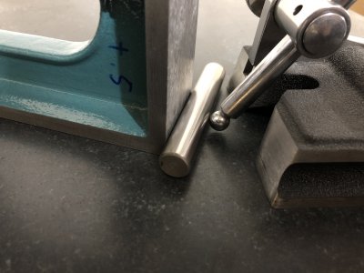
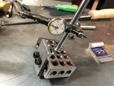
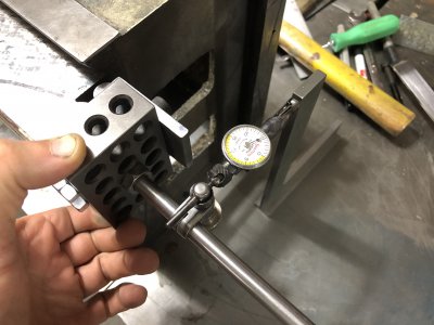
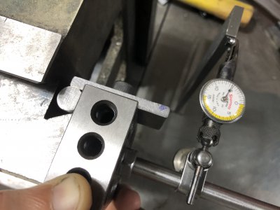
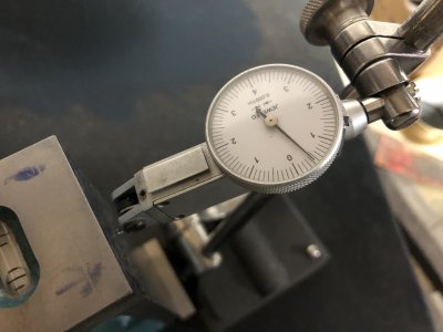
Andy: Unrelated to the mill, but one point about checking squareness. This photo shows you laying the dowel pin on its side:
View attachment 341258
I believe the better technique is to place the pin
on end, registering in a vee at the front of the indicator base. You then sweep the indicator, looking for max deflection with base, pin, and square all remaining in contact while rotating the base. You can also use a steel ball in a vee, or simply attach a semicircular bearing plate to the front of the base. In other words,
point contact is better than
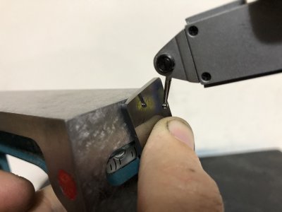
line contact. I'd also draw a line parallel to one edge of the square with a sharpie and ensure the dowel pin and indicator tip are both touching the same line. The surface of the square is a plane that can be tipped on
two different axes. You want to use your indicator as squareness comparator of a single
line on that surface. Think:
points to establish a
line that sits on the
plane. The pin-on-end registering in a vee gives you three-point contact at the base of the line you're verifying, and the indicator tip establishes the point at the other end of that line.
I'm sure you fully understand, but for completeness: The process I'd use to check a precision square is to first verify that two opposing faces are truly parallel (checking all four corners and the center of the top face with the indicator referencing from the same plate, as you've done). Then I'd draw a line a fixed distance from the edge of an orthogonal face (one of the faces you're testing for squareness). I'd then adjust the indicator so the dowel pin and indicator tip both touch the same line, sweep to find max deviation, and zero the indicator. Finally, I'd turn the square upside down, reference points on the same line, and sweep for max deviation. Any non-zero measurement indicates double the error.
I doubt you'll measure very different results if it's out several thou (which is shocking, tbh) but it does matter when you are checking something that's gage quality (tenths).


 .
.