- Joined
- Feb 1, 2018
- Messages
- 1,868
Yes I thought of you while I was writing that,

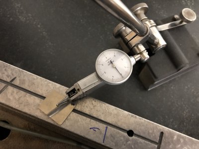
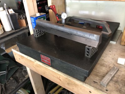
Basically what I did was lay the dowel flat, but sweep using the ball end of the indicator [against the dowel], and look for maximum height.
Ah. I see.
Yes, for a scraped surface you want something to average out the scraped points. I think a gage block or parallel might work better, though, and is more commonly used for the purpose. I'd rather have the ball against a plane than against a cylinder. Any vertical discrepancy will translate to a horizontal discrepancy with the latter. The carbide blade you used at top is probably flat and parallel (but I'd still check it!).
I've tried using the ball at the end of the indicator stand rod to test squareness, but without much success. Rich told me that's indeed it's intended purpose, but it's so small that it's tricky to get an accurate reading. I slotted the front of my indicator base to hold a small plate with a curved front and use that for the purpose (the curve doesn't even need to be terribly accurate — belt sanding or filing a fair curve suffices). That or a large steel ball held in a vee works better for me.
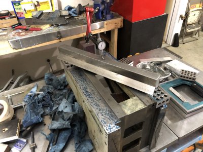
I think you should get your plate re-ground and calibrated if you don't trust it, though. You're almost certainly fooling yourself if you think you've made something more accurate than the plate by scraping it in relative to the plate! If the part hinges well on one part of the plate but differently on another (and you've ensured everything is spotlessly clean) then there is no way to know which area is truly flat (probably neither).
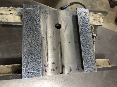
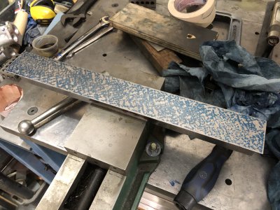
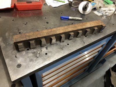
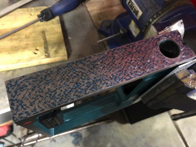
Thanks man, it's getting there, very slowly though. Have a day job and don't have a lot of time to work on this.fantastic work, that'll be a cracking mill by the time you're done. Any plans on doing the head/ knuckle junction? I remember reading about someone else scraping in a small knee mill like this and that was another area that benefited from some work. How long did it take you to machine your straight edge to rough shape? Looks like a decent sized lump of CI!
If you want to get fancy about it, you send it out to get thermally stress relieved. In a home shop, you can shot peen it , or hand peen it with a hammer. That would cause many stressed lattice dislocations that are susceptible to move to move. Or you can leave it outside for a while.How does one know when a piece of metal is fully "relaxed" and not subject to movement as time goes by? If there are stresses in the metal and part of it is removed then the stresses will cause the metal to change shape. I've seen this in cast iron.