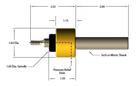
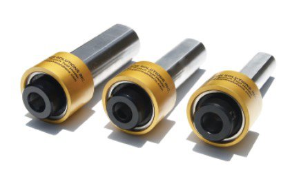
Group Project: Rotary Broach-- Building complete, all shipped out!

I like you design but I have one question. Is there something that retains the spindle so it doesn't get pulled out? When I use my broach, the cutter sometimes gets stuck in the hole and traction is required to remove it. There could be significant pull on the spindle.
Robert

EDIT: Never mind! I missed part #9 the clip. That looks good.
Robert
 
The no center broach was the same place as the link you gave for $50 bits.
What type of steel? I agree, not a lot of beatings going on here, but I would think bearing surfaces should be hard/hardened...if we plan on making this a quality tool that is handed down and such.

no center.jpgno center2.jpg
 
I like you design but I have one question. Is there something that retains the spindle so it doesn't get pulled out? When I use my broach, the cutter sometimes gets stuck in the hole and traction is required to remove it. There could be significant pull on the spindle.
Robert

EDIT: Never mind! I missed part #9 the clip. That looks good.
Robert
Yep, there is a snap ring at the back of the spindle :) The bit is held in by a set-screw, though I want to do some slight changes to the model (hopefully not making it too much longer!) to make sure it hits the 'flat' right on most commercial bits.


The no center broach was the same place as the link you gave for $50 bits.
What type of steel? I agree, not a lot of beatings going on here, but I would think bearing surfaces should be hard/hardened...if we plan on making this a quality tool that is handed down and such.

View attachment 369033View attachment 369034

I don't see hardening the surfaces as necessary, we have hardened races on the bearings, so those should be the frictions surfaces.

I looked at that design quite a bit, and I just don't see how they get away with no adjustment unless they are simply counting on more accurate machining/tool lengths. I calculated that every 'thou' is worth quite a bit in length, which makes me think the calibration is just less important than a lot of these youtubers are making it seem. Based on my math in a post a bit above, Each 'thou' of offset covers something like 50 thou of length.

2.5" is 43.6 thou, 2.6" is 45.4 thou offset, so I suspect the calibration is just way less important after the 1st time than the drawings all seem to make it seem.
 
  • Like
Reactions: rwm
I now think you are correct about the precision of the offset not being so critical. The Sine of 1 deg is a pretty small number and there is some flex in any setup. Your design is gonna work great.
Robert
 
I now think you are correct about the precision of the offset not being so critical. The Sine of 1 deg is a pretty small number and there is some flex in any setup. Your design is gonna work great.
Robert
Thanks for the confirmation! I'm thinking of simplifying the back plate to remove the slots and replace with slightly oversized holes instead (plus the built-in-offset), since that should get us close enough.
 
The amount of offset you will need should be Sin 1 x length from backplate to tip of broach. That would tell you how much adjustment you will need. What is that distance?
R
 
Last edited:
The amount of offset you will need should be Sin 1 x length from backplate to tip of broach. That would tell you how much adjustment you will need. What is that distance?
R
Yep, that's the math I came out with. Currently in the design it is 2.5061" (if I remember correctly) for 43.7 thousandths.

I had designed in a adjustment range of 150 thou (plus the fit of a 1/2-28" in a 1/4" hole), but reduced the slot to .35" as the design finished. I suspect I'd be better off making it an F or G instead, and simplifying @GunsOfNavarone s work!
 
  • Like
Reactions: rwm
Maybe some ideas....
Broach
Also some good info on making the actual cutting bits.
I actually got that in my feed a few days ago :) My plan was going to be to rough it out on my bench grinder (for the smaller bits), then finish using my magnetic sine plate (with a machinist vise on it most likely), then use my hex/square collet-blocks to get the angles right. Overall size is easy enough to get it seems, it is just a matter of sneaking up on it I expect.
 
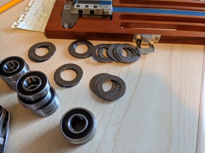
Good news! Bearings all showed up today and measure about what I hoped they would! I have a couple small changes to make, but I should be able to start on 2d drawings this week!


Also good news.. I played with it a bit and took about the OAL down another 70 thou. There is a spot to take it down another perhaps 150 thou, but I like the 200 thou wall between the back of the broach and the rear bearing.

I still need to adjust the offset because of that, and fixup the holes on the backing plate, then I can start drawing :) We will see how this goes, I'm excited to see how well the design holds up against reality.
 

Attachments

  • PXL_20210613_212213790.jpg
    PXL_20210613_212213790.jpg
    3.1 MB · Views: 7
Last edited:
Back
Top