- Joined
- Jun 26, 2018
- Messages
- 1,733
I see you are crunching numbers on shortening the OAL. I was considering allowing some extra thickness on the backing plate so no matter if the arbor is .625 or .750 long (threaded shank), it could be tightened down with no worry of bottoming out. Also, I now the off center is taking up it's part of the pre planning, what if the backing plate had a boss and the spindle body was recessed and you could have 4 sets screws around the outside for centering?
I.E. below. The boss could still be ground with the 1* of angle

I.E. below. The boss could still be ground with the 1* of angle
Last edited:
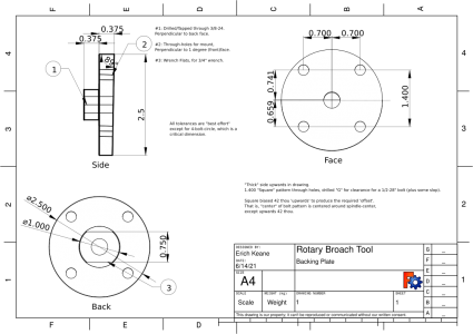
") The 1 degree angle confuses the heck out of the drawing panel in a number of different ways!
The 1 degree angle confuses the heck out of the drawing panel in a number of different ways!