

-
Welcome back Guest! Did you know you can mentor other members here at H-M? If not, please check out our Relaunch of Hobby Machinist Mentoring Program!
You are using an out of date browser. It may not display this or other websites correctly.
You should upgrade or use an alternative browser.
You should upgrade or use an alternative browser.
Group Project: Rotary Broach-- Building complete, all shipped out!
- Thread starter ErichKeane
- Start date
- Joined
- Jun 26, 2018
- Messages
- 1,733
I guess that an issue to discuss. When I started the “this madness needs to stop” thread, the purpose was to get people to (if they haven’t much or all) to learn to work from blueprints with tight tolerances. That way a part Dave made would fit flawlessly in a part Mary made. It getting the feeling that everyone is just going to make there own broach? One person is making all of X part(s) and someone else is making Y part(s)? We probably need to work this out as it maybe a group build or a group making the same thing at roughly the same time.
Depending how this is done, there maybe plenty of room for @Ianagos or may not be.
Depending how this is done, there maybe plenty of room for @Ianagos or may not be.
- Joined
- Aug 3, 2017
- Messages
- 2,437
>>One person is making all of X part(s) and someone else is making Y part(s)?
I was hoping for this, based on the purpose of the original thread") I liked this project since the parts-list was so much lower than the dividing head, but apparently we have more interest than parts
I liked this project since the parts-list was so much lower than the dividing head, but apparently we have more interest than parts
Would there be interest in doing _2_ groups?
I was hoping for this, based on the purpose of the original thread
I liked this project since the parts-list was so much lower than the dividing head, but apparently we have more interest than parts Would there be interest in doing _2_ groups?
- Joined
- Jun 26, 2018
- Messages
- 1,733
I'm down for whatever. people taking on responsibilities that match there skill/equipment. People pushing themselves and taking on things they are weak at (to learn)
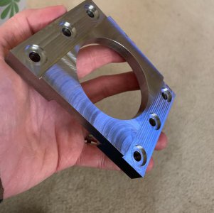
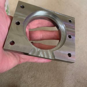
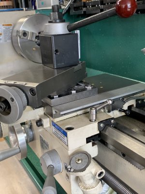
As that first thread got away from me, I went out and found what I needed. I made a 6 bolt compound clamp out of A2 tool steel. I found the plans here and rated myself on out come of measurements. Sub a thou and now my lathe has new life with higher rigidity.
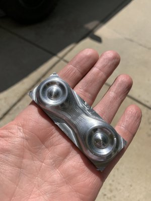
I also upped my F360 game and CNC work with some complex designs (again in A2)
You gotta push yourself and get outta of the ruts...you’ll be a better “machinist” in the end.
As that first thread got away from me, I went out and found what I needed. I made a 6 bolt compound clamp out of A2 tool steel. I found the plans here and rated myself on out come of measurements. Sub a thou and now my lathe has new life with higher rigidity.
I also upped my F360 game and CNC work with some complex designs (again in A2)
You gotta push yourself and get outta of the ruts...you’ll be a better “machinist” in the end.
Attachments
I guess that an issue to discuss. When I started the “this madness needs to stop” thread, the purpose was to get people to (if they haven’t much or all) to learn to work from blueprints with tight tolerances. That way a part Dave made would fit flawlessly in a part Mary made. It getting the feeling that everyone is just going to make there own broach? One person is making all of X part(s) and someone else is making Y part(s)? We probably need to work this out as it maybe a group build or a group making the same thing at roughly the same time.
Depending how this is done, there maybe plenty of room for @Ianagos or may not be.
Well I’m very familiar with working from prints no worries there.
I just like these projects as they are something different from the typical work I do.
If there is no room for me it’s not an issue at all.
- Joined
- Aug 3, 2017
- Messages
- 2,437
So I'm playing with that design like TomMakeHere did in the design we talked about above. I was trying to modify it slightly to use imperial bearings (not particularly possible with the front needle bearing), but I'm also not a fan of how the body needs to be formed in order to use 2 bearings. There is a double-flat internal dimension where the distance between the two flats its pretty critical. It seems to me that it would be a pretty nasty dimension to hit, particularly in the sizes we're talking about.
Instead, I have 2 options:
1- I go with a longer needle bearing at the front, and count on THAT to control the 'sheering', then just the thrust bearing at the back. It is perhaps a little suceptible to radial forces as the 'back' is unsupported in that way (though ~1" of support at the front).
2- Do those (perhaps the 3/4 needle bearing still at the front), but replace the thurst bearing/normal bearing with a taper-roller bearing. GunsOfNavarone posted above about a 1/2" one that would work fine, if a little large, resulting in a slightly larger diameter body.
I could optimally use a 3/8" ID taper roller bearing, but I couldn't find any cheap ones.
Additionally, I'd like to add 2 features, which I think I'd like to hear feedback from the builders/others!
1- Some sort of grease nipple. TomMakesHere's version (the fluted one in the video above) looks like it requires ocassional disassembly to grease the needle bearing and thrust bearing. He has to do this because his normal bearing on the back ends up being sealed. Even in his design I think I could put a grease nipple on the body.
2- calibration screws: Once you've got it assembled, you have to get the offset on the 1 degree taper right-on to make sure the 'points' of your bit are all the same 'height'. The one in the original-post uses a couple of adjustment screws to do so, TomMakesHere suggests just 'tapping' it in after loosening the bolts. I'd love to do the adjustment screws if I could find a place for them.
So, thoughts/feedback? Anyone have a 3/8" ID taper roller bearing I could design this around?
- Joined
- Jun 26, 2018
- Messages
- 1,733
I have never owned or used a rotary broach, so my input is shooting from the hip. It seems many I have seen are completely disassemble. If your talking about one that requires a zerk because once you build it, you're never getting back into those bearings.....I'm not a fan. The adjustment screws; I am a bit confused (though I have seen those) why it can't be made with zero offset so it doesn't need that, and rely on the base plate being made with 1* of angle to facilitate the in/out broaching action.
I guess the bearings used would be solely based on design choices, but whatever is needed. Being we are making a tool that would cost 100's of dollars, I don't mind spending 20, 30 or ? dollars on bearings. I wouldn't take anything out of the mix because the bearing seem expensive (of course I don't know what too expensive was in this case.
I guess the bearings used would be solely based on design choices, but whatever is needed. Being we are making a tool that would cost 100's of dollars, I don't mind spending 20, 30 or ? dollars on bearings. I wouldn't take anything out of the mix because the bearing seem expensive (of course I don't know what too expensive was in this case.
- Joined
- Aug 3, 2017
- Messages
- 2,437
This would still be able to be taken apart, the point of the zerk is so you don't have to! My plan still has the bolts-to-the-backing-plate + cir-clip construction, but it means you don't have to take those apart (and perhaps lose your calibration) in order to grease it. A part of me suspects it is just superfluous, as we aren't going to be using these that much...I have never owned or used a rotary broach, so my input is shooting from the hip. It seems many I have seen are completely disassemble. If your talking about one that requires a zerk because once you build it, you're never getting back into those bearings.....I'm not a fan.
So the point of the adjustable offset is to make up for the 1 degree angle. The idea is that as the broach-bit rotates, the cutting points need to all be the same distance from the center-of-the-machine-spindle, otherwise you cut an off center or oblong broach. If you check out the 'troubleshooting' guide in the 3rd image here, it explains it a bit: https://www.etsy.com/listing/831959563/rotary-broach-plan?ref=shop_home_active_1The adjustment screws; I am a bit confused (though I have seen those) why it can't be made with zero offset so it doesn't need that, and rely on the base plate being made with 1* of angle to facilitate the in/out broaching action.
You'll see from that guide, he shows that you can loosen the mounts and 'tap' it into alignment, though I'm not sure I'm a huge fan of that. I always do a really terrible job trying to tap things in
I guess the bearings used would be solely based on design choices, but whatever is needed. Being we are making a tool that would cost 100's of dollars, I don't mind spending 20, 30 or ? dollars on bearings. I wouldn't take anything out of the mix because the bearing seem expensive (of course I don't know what too expensive was in this case.
The 3/8" bore ones i found were pretty costly, like $120 for a bearing. I can keep looking though.
- Joined
- Aug 3, 2017
- Messages
- 2,437
FWIW, I just figured out the Hemingway Kits design Stefan G's video shows a cross-section:
I'm not a huge fan of it not being all that adjustable, and the idea of cutting a 1 degree taper inside a bore seems pretty awful (and requires a mill). That said, it looks like it uses a thrust bearing and 2 normal bearings.
It DOES have a good idea in that the tool-holding spindle has a bore out the back, which is super nice for knocking out the tool if you get it stuck!
Stefan G's video shows a cross-section: I'm not a huge fan of it not being all that adjustable, and the idea of cutting a 1 degree taper inside a bore seems pretty awful (and requires a mill). That said, it looks like it uses a thrust bearing and 2 normal bearings.
It DOES have a good idea in that the tool-holding spindle has a bore out the back, which is super nice for knocking out the tool if you get it stuck!