Group Project: Rotary Broach-- Building complete, all shipped out!

It's not the shank itself, it's the bearing block attached to it that the apparatus spins on...no?
 
This appears to be a pressed fit...hell, you could possibly buy whatever arbor and press fit it....though that's technically cheating.
angle plate.jpg
 
My thought was 1/2" for chuck compatibility. It is true that the tool hanging out there might be an issue on smaller machines though.

I do have a R8/MT3 adapter I've used occasionally for drill chucks on the mill.

The taper on the print shows an M12 thread on the back. Drawbar?
 
This appears to be a pressed fit...hell, you could possibly buy whatever arbor and press fit it....though that's technically cheating.
View attachment 368825
Ah, I took that to be 1 piece. I guess that could be press fit... though I would have thought he would have a separate drawing for separate pieces. But yes, that part on the left of the picture introduces the 1 degree taper.
 
Here is my take on that rotary broach, with a few of the changes that I wanted to do (still doesn't have the 'adjuster'), and some of the dimensions aren't perfect.

The green piece is the broach-bit.
The transparent bit is the 'body', which you can see holds everything. It has some slotted screws so we can do adjustments.

The broach-bit goes into the spindle, which sits against the teal "needle thrust bearing", then goes through the 'body' and into the roller-bearing in the back. What you can't see, is a retention clip holding it together.

broach6_10.jpg

I still have to make the flange/rear plate, plus figure out how to do the offsets. Additionally, I probably need to spend a good while making all the dimensions 'right'.

BUT, that is my design so far.
 
  • Like
Reactions: rwm
Here is the back view, which should be a bit more clear.

6_10 back view.jpg


Since we have quite a bit of question on the back plate/shank, I think I'll make it be 2 parts, and threaded together. How does that sound? That way if you find yourself really wanting an MT2 mount, you can just thread the adapter on!

I want to pick a thread, which would you prefer? https://www.amazon.com/Morse-Taper-Adapter-Shank-Threaded/dp/B07W9L13RS?th=1

Looks like there is 1/2-20, 3/8-24 and 5/8-16. I'm leaning toward 3/8-24 unless someone wants to go bigger-enough on the MT scale that it would be a problem. Currently, I found an MT4 for 3/8-24 (https://www.amazon.com/Threaded-Drill-Chuck-Hardened-Adapter/dp/B015NMGBF2), so I figure that should be big enough, right?
 
Sounds like a reasonable approach. Looks like plenty of surface area to register against, though I'm not sure concentricity is important for something you want to wobble about anyway. You could make it nice and straight if you want to!
 
Only current 'downside' to those adapters is I can't figure out how long the threaded section is! Even the mcmaster version doesn't have a CAD drawing!

Unless someone orders one in advance, I'm going to have to guess. Worst case, you might have to grind a bit off of it.
 
So another thing I did... Currently the "OAL" of our tool not including the backing plate, but including the tool-bit is 2.5061. That actually ends up being SHORTER than the tool that GunsOfNaravone posted that I've been copying off of (which is 66.6mm/ 2.622"). This is despite using a slightly larger bit at 1.75" vs 35.6 mm (1.401").

I believe this means our 'offset' that we have to have against the backing plate is ~.044. He only has 1.1mm built in (~.043"?), so I think he's counting on the oval screw-holes by quite a bit, because my calculation ends up putting him at nearly .046"?

Does someone want to check my math? Again, tip of tool to base of flange (excluding backing plate) is 2.5061. Angle is 1 degree.

Either way, this is quite re-assuring that we don't need much in the adjustability range. I think I made those ovaled holes something like 30 thou in each direction! In reality, if 3 thou offset covers 60 thou in length, we don't have much to be concerned about!
 
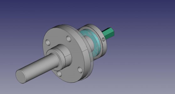
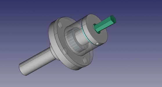
Two more pictures! If anyone wants to view the design in any format i can export (see Std Export here: https://wiki.freecadweb.org/Import_Export) let me know, and I'll post that too! Just be kind, its only my 2nd time doing CAD.

I never put in the 'calibration' mechanism, as you guys never seemed interested in it I can put those in somewhat easily (it complexifies making the backing plate a bit...). I'm somewhat convinced 'tapping' it in should be easy enough.

I have 2 more TODO's on this diagram:
1- I want to make the bolts come in from 'behind', it gives more room for the heads, as well as makes the math for the backing-plate less critical.
2- Wrench-flats for the backing plate.

I think the next step I want to do is order bearings to measure them and make sure of my dimensions.

Also, out of the 4 of us (
1- ErichKeane
2- GunsOfNavarone
3- ttabbal
4- T Bredehoft)

We have to decide who is going to do which part. Basically, you buy the materials and make your part, ship them to someone who assembles and ships. Let me know what part you want to do, and we can sign up for them. I can modify the design/some details based on equipment if you'd like.

1: Backing Plate : has an internal 3/8-24" thread, plus a 1 degree angle on the front, plus some corresponding holes. Requires about a 2.5" round of steel, each part is ~3/4" long.
2: Main Body: About 2 1/8" in diameter, less than 1 1/2" long. There are two precise internal pockets from opposite sides, the dimensions of which are somewhat reasonably meaningful, plus some tapped 1/4-28 (or 1/4-20, not sure it matters).
3: Spindle: 1-1/2" diameter 1-1/2" long. Requires a somewhat precise 3/4" deep, 1/2" flat-bottomed hole, plus 1 fairly precise OD. Otherwise not too bad.
4: Grinding of tool bits. 1.750" long HSS, requires a pretty accurate grinding setup, probably a surface grinder.

As far as overall cost, there is the above materials + shipping them to me, plus:
Total cost of other parts should be cheap, I kept us to a #10 set screw, a thrust bearing ($8 for 6!), a sealed roller bearing ($9/10), a snap ring (2.35/10 + mcmaster shipping https://www.mcmaster.com/98585A109/ if someone can find an amazon link:)), and 4 1/4-20 or 1/4-28 bolts.


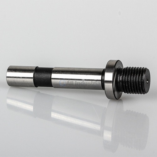
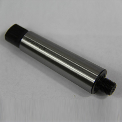
Additionally, I think we should all just decide to order our own shanks. It looks like they are available for ~$10 each, even 1/2" arbors are available at all-industrial, as well as MT 1, 2,3, and 4 AND R8!


Total non-materials/shipping out of pocket:
set screw: $.50 (Guessed!)
Thrust bearing: $2 ($8 for more than we need)
Roller bearing: $2.25 ($9 for more than we need)
Snap Ring: $1 (2.35 + mcmaster shipping for more than we need)
4 bolts: $2 (another guess).
Arbor: $10
===========
$17.75.
$7.75 of which I will pre-order, so that plus whatever a flat-rate box will cost is your amount you'll eventually owe to me when we're done.
 

Attachments

  • 6_11_back.jpg
    6_11_back.jpg
    126.3 KB · Views: 10
  • 6_11_front.jpg
    6_11_front.jpg
    130.7 KB · Views: 9
Back
Top