Harbor Freight 90a Flux-core Ac To Dc Conversion

Several (>10) years ago I came into posession of some individual diodes of high current capacity. They were pulls from an industrial DC crane feeders, some 500 Amp, 1000 Volt rating. Being individual components, they took up a lot of space. But, installed in a Lincoln 225, the space was there. I built the bus-bars of 1/2" copper tubing, flattened, into a full wave bridge. And appropriate insulators, of course. The results were impressive, to say the least.

I have worked around DC machines for my entire life. The man who taught me to weld way back when, would write his name on the sheet metal siding on the building, without blowing any holes. Told me when I could do that, I could call myself a welder. Haven't made that yet, still working on it. The point being that with welders, DC is the way to go, regardless of size. Such a conversion is well worth the cost, in time or money, however you figure it.

On my Lincoln, I have yet to overheat the transformer from high duty cycle. Conceded, most of my work uses only two or three rods. But have increased the duty cycle at least double. How much more I'm not qualified to say. I have tried several times to use wire welders. Most times I just give up and revert to the stick.

Bill Hudson​
 
I am glad I'm not the only one that has problems using a wire welder. Yesterday I was making some home-brew jacks that required welding some 3/4" bolt heads to steel plates. The welds came out pretty horrid looking. Oh well, at least the bolts are stuck down....which is all that's necessary in this case.
 
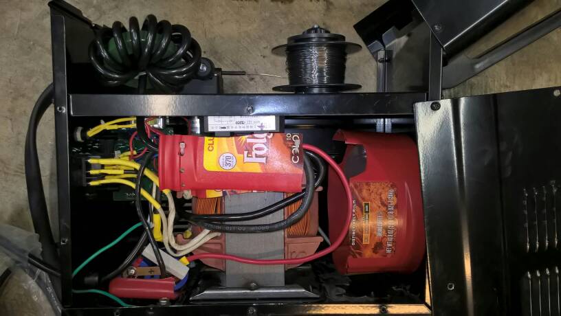
Sorry to dredge up an old thread. Just finished the conversion with parts that I've had for over a year. 100amp 1000volt rectifier (I feel the 150 amp 3 phase probably are not fully 150 amp on one phase), 2 paralleled 33000 mfd 50 Volt caps. I used 4 AWG for hook up to/from rectifier and through the choke, which is only 12 turns through a ferite ring. Used 6AWG to connect to the caps (flattened 1/4" copper tubing to join them) with the 50 ohm 10 watt ceramic resistor across them. Recitfier is mounted on ~2"x 6" x 1/2" aluminum plate with high-dollar heat paste that I had a bunch of left over. That is mounted under the mid-deck beside the xformer. The choke (on the +) is up with the wire feed and tapped into the electrode line there. Caps in front of the xformer on the bottom. A Folgers plastic coffee bucket was cut up and used as a fan shroud, and as extra insurance against undesired shorts.

Haven't tried it yet, maybe tomorrow if weather holds.
 
Not pretty. Doesn't need to be.
fa78b8304a5ab14579086641febd0739.jpg
 
Tried it today. Much better than before, but found that I have to cut the wire right at the exit of the torch. This gives a short delay before the wire makes it to the workpiece, giving the cap time to charge. Otherwise, it just sticks to the workpiece and doesn't start arcing. Did a ~2.5" bead without hitting overload. A lot less sputter and better penetration.
 
I haven't noticed problems with the wire sticking to the workpiece. Unlike your mod, I didn't add a series choke. The choke would reduce the initial current flow so that could explain the difference.

The choke also would smooth out the current flow so overall it should work better -- if I feed the wire too slow, the capacitor charges up enough to blow the wire up in a series of "bangs". Faster feed rates seem to work OK.
 
What are the details of your shunt resister, "OP"?
I apologize if you have addressed this in your article; I was just curious. I am aware that this is an old post.
 
The cap for my conversion included the resistor, I don't recall the ohms. Here's a YouTube video of one of the conversions I watched. He mentions 470 ohms in the video, but I didn't hear the watts. Looks to be pretty hefty, maybe 10 - 20W.

Bruce


I used a 10 watt 260 ohm resistor in my conversion. Not being an electrical wiz I don't remember why I picked that size. It must have been the size recommended by videos that I watched on how to do this.
 
IIRC, I used something around 500 ohms. Point is, it's not critical. It is just meant to discharge the capacitor so the voltage drops pretty quickly, to avoid a shocking surprise later <g>. The value also depends on how large the capacitor is -- the larger its value, the slower it discharges for a given shunt resistor value.
 
Back
Top