I've been chasing Z axis ball screw/ball nut backlash for quite some time on my PM-932 CNC mill and have narrowed the main source as the ball nut mount/ball screw sleeve (items 14 and 15 in the attached assembly drawing) and the attachment to the headstock base casting (item 4). As you can see the lead screw nut sleeve slips into a oval slot in the headstock base casting and is fastened in place with a socket head cap screw and a thick flat washer (items 26 and 27). The lead screw nut, which I've modified to accept a ball nut (photo attached), has a cylindrical spigot that slips into the lead screw sleeve. As best as I can determine this setup is similar across most, if not all, RF-45 and ZX-45 type vertical milling machines. It may be applicable to other styles of milling machines but I cannot say with any certainty. While this works well on manual mills the slip fit interfaces are a source of backlash when converting to a ball nut and ball screw.
Before anyone asks I've installed a Z axis double ball nut that I've fine tuned by adding a .002" shim between the two nuts to take up any pre-existing backlash, made sure the AC bearings are properly preloaded and lubricated, and installed a double disc coupling to eliminate coupling flex. I've attached a picture of my Z axis bearing/motor mount. As you can see it's stout so no flex there.
I have a conceptual design in my head where a one piece mount with a flange will bolt to the back side of the headstock base casting thus eliminating clearance between the lead screw nut sleeve and the oval slot and the clearance between the sleeve and the lead screw nut. I realize I will no longer be able to tilt the head but I am willing to accept this limitation if it eliminates the backlash. I've also thought about drilling through the sleeve and nut mount and reaming for a taper pin but I'm not convinced it will be a long term fix.
So on to my question. As the title of this thread says I'm searching for any lead screw nut mount modifications on these styles of mills. I've done a Google search but didn't find anything relevant. Rather than start from ground zero I thought I'd query the resident brain trust before diving in.
Thanks for listening.

The cylindrical spigot slips into the lead screw sleeve. It is a snug slip fit.

This is the sleeve mounted to the back side of the headstock base casting.

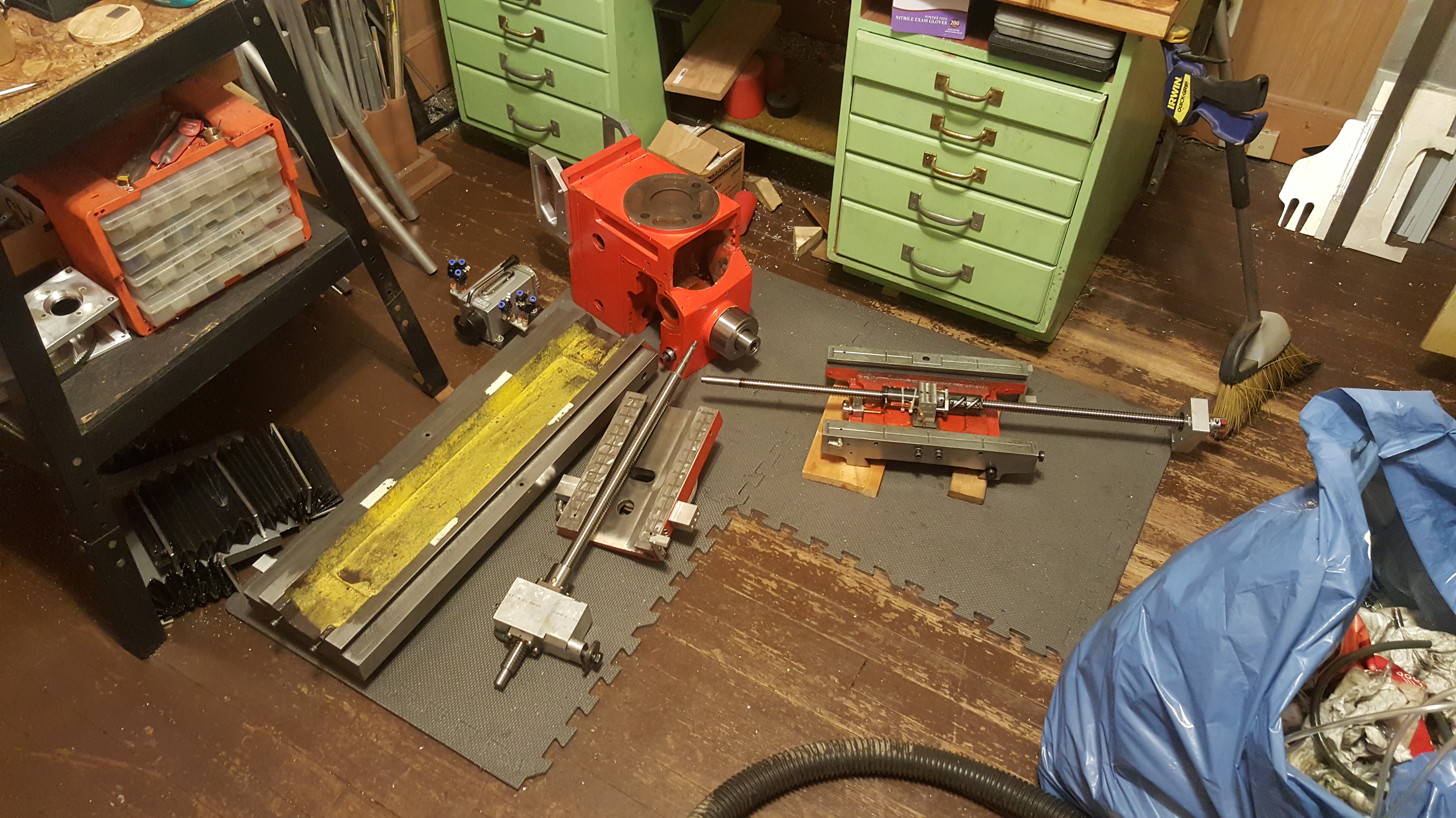
The base plate is 1" thick aluminum plate and the box is made from 3/4" thick plate. The box bolts to the plate with eight 1/4"-20 socket head cap screws.

Before anyone asks I've installed a Z axis double ball nut that I've fine tuned by adding a .002" shim between the two nuts to take up any pre-existing backlash, made sure the AC bearings are properly preloaded and lubricated, and installed a double disc coupling to eliminate coupling flex. I've attached a picture of my Z axis bearing/motor mount. As you can see it's stout so no flex there.
I have a conceptual design in my head where a one piece mount with a flange will bolt to the back side of the headstock base casting thus eliminating clearance between the lead screw nut sleeve and the oval slot and the clearance between the sleeve and the lead screw nut. I realize I will no longer be able to tilt the head but I am willing to accept this limitation if it eliminates the backlash. I've also thought about drilling through the sleeve and nut mount and reaming for a taper pin but I'm not convinced it will be a long term fix.
So on to my question. As the title of this thread says I'm searching for any lead screw nut mount modifications on these styles of mills. I've done a Google search but didn't find anything relevant. Rather than start from ground zero I thought I'd query the resident brain trust before diving in.
Thanks for listening.
The cylindrical spigot slips into the lead screw sleeve. It is a snug slip fit.
This is the sleeve mounted to the back side of the headstock base casting.
The base plate is 1" thick aluminum plate and the box is made from 3/4" thick plate. The box bolts to the plate with eight 1/4"-20 socket head cap screws.