You have several options.
1. Replace the current contactors with new ones or relays of the same voltage, remove the high voltage motor connections to them and connect one pole of the relay/contactor to the corresponding VFD For/Rev. input, this is similar to the basic 1340GT VFD install posted. DO not attempt to use used contactors (or any contact that has been used for high voltage switching) to operate the VFD inputs, due to arching they have high contact resistance and will give unpredictable transmission of the low voltage VFD signals.
2. Some people directly wire the VFD inputs (For/Rev) to the spindle switch and add an additional input which prevents the VFD from starting on power up if in a run command, but if you hit the E-Stop and then release it the machine will restart. Dangerous in my opinion to directly wire the VFD inputs to the spindle switch in any form.
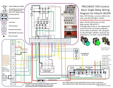
3. There is an old single relay design that used the VFD's internal 24VDC power source to run the relay. It had limited flexibility and the total power consumption needs to be less than 100 mA. A 24VDC relay is around 70 mA, a LED lamp is around 11 mA. Below are some very old designs that have been used, but use at your own risk. These are starter points that would need to be adapted to your specific machine, some of the programming is different depending on the application.
4. There are full system designs, but much more complicated.
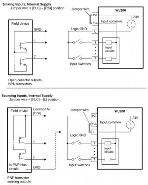
Your question as to input jumper position on the WJ200, the PLC/L is what as none as sink inputs and the L/P24 is known as source inputs and has to do with the polarity direction of the inputs in relation to the power supply. Systems that use the WJ200 internal VFD power supply to power a relay, LED, etc. OR you are using diodes which prevent back feeding such as below OR the PLC setting is source, require you to use the source configuration. Almost all VFDs by default are factory set for the sink configuration most have the ability to change this to a source configuration.


