Headers for my MG Midget

mickri

H-M Supporter - Diamond Member
H-M Lifetime Diamond Member
Joined
Oct 31, 2016
Messages
2,643
I have been slowly resurrecting a 1966 MG Midget.
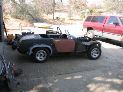
IMG_3506.JPG

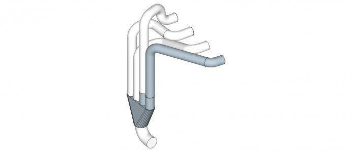
The original engine made less than 50 hp on a good day and the one in my car was frozen solid. In stead of paying thousands of dollars to have it rebuilt I am swapping a running Toyota 3 TC out of a 1982 Corrola into the midget. Current project among too many to count is headers. Others who have done this swap have ran the tubes over and under the steering column. If you have to remove the headers you have to take out the steering column. Every one who did this forgot about R&Ring the starter only to discover after the fact that they couldn't get the starter out without removing the headers. To avoid this you have to snake the tubes over the steering column and then down through a 3" x 7" slot between the steering column and two frame rails. Further complication is that from the edge of the exhaust port to the center of this slot is only 6". I did some mock ups with pvc pipe and thought I had it figured out. As a cross check I took really accurate measurements and did some 3d models in sketchup. What I thought would work was not even close. After countless hours on the computer I finally have a design that will work. I hope. Next I need to finish the exhaust flange and order the tubing and collector. Here's my latest and hopefully final design.
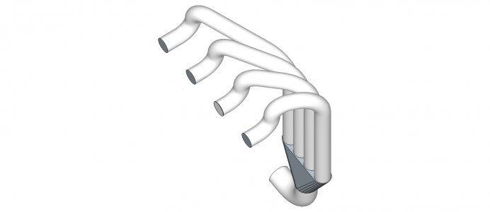
4-1 header ver 05.jpg
 
I got one would love to see it made. Are you going to use stainless? Are you going to weld it up?

joe
 
I had a Bug-Eye Sprite with a race prepped Mazda RX4 motor, a 1300# with about 200+ hp, I had to sell the car, the mixture of a high hp/weight ratio car, a foolhardy young kid, with alcohol issues, was a recipe for death.

with your design, how close are the tubes in equal length??
 
Definitely watching your progress @mickri!


Sent from my iPhone using Tapatalk
 
The tubes aren't even close to being the same length. The number 1 & 2 tubes are almost the same length but the #3 & #4 tubes are way longer. Especially the #4 tube. I originally tried to work out a 4-2-1 header because this is just a street car with a basically stock engine. 75 to 80 hp. And I wanted low end street performance. Down at the bottom of the slot there is only room for one tube to exit the engine bay. That nixed the 4-2-1 design.

I ran the formulas for tubing length and size. Those recommended 1 3/8 tubing a little over 30" long to a 1 3/4 pipe back to the muffler. I can meet the tubing sizes but not the length. I was lucky to find a flat collector for that size tubing. The other thing that was tough to find was mandrel bends with a 1.5" radius. Only one place sells those.

Not going to use stainless steel. Besides the additional cost I don't have the ability to weld stainless steel. Still undecided if I will tack everything together and then have the local muffler shop weld it up or try to do it all myself with my HF flux core welder. It has been modified to be DCEN. The local muffler shop gave me a bunch of scrap exhaust tubing to practice on. I will do a lot more practice to see how good I can get before making a decision on the welding. Doing ok so far on the welding practice.

Should be a fun car to drive. I am also using the 5 speed out of the toyota. The 5 speed gives me good low end and the overdrive 5th speed will keep the revs within reason on the freeway.

I bought a complete running car for $450 delivered to my house. After I stripped everything off that I wanted the scrapper came back out to my house to pick up the remaining hulk.

Goal is to have it running by next summer.
 
Off the wall thought about gluing some of the joints in the headers. Some of the joints in my headers are straight butt joints. You can now buy glue that withstands over 2000 degrees. On these straight joints I have thought about making a slip joint with the high temp glue. Easier than welding and if it fails I could always weld it.
 
That's an impressive model, I'm still amazed at what is possible these days on a home computer. It wasn't that many years ago that it would have taken a highly trained CAD jockey with computer the size of a walk-in freezer to create that. Did you also model the engine compartment? If so, I'm curious about how you did your 3D measurements. I used to occasionally do measurements for reverse engineering , but we had portable arm CMM to use.
 
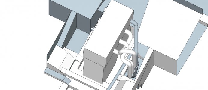
I have an accurate 3d model of the engine bay with a rough drawing of the engine in place. But the engine is not quite exact enough to stick the headers to the engine.

I use google sketchup. To draw the individual tubes I first draw a line that is the path where the tubes go and then use the follow me command to draw in the tubes. Spent an ungodly amount of time this morning trying to see how close I could get to have the tubes be equal in length. I was a able to get the tubes within an inch. The tubes are 22.33, 21.52, 21.27 and 22.22 inches in length. I might be able to shorten the longest tubes by .433" by using a 2.5" radius bend instead of a 1.5 radius bend where the tubes turn to go down to the collector. Here is the latest

4-1 header ver 06.jpg
 
Stuck the headers into the engine bay.

spridget engine bay with 3tc.jpg
 
You really don't want a 1.5" radius bend in your primaries, do you? I've seen the length you Brit car guys go through to stuff a header through that small gap, and they often break the rules for ideal primaries and collectors. Will it still work with 2.5" radii? Are you stepping your primaries, or going straight I.D. all through? Is the length of your head pipe that comes straight out from the head compatible with the short turn radius of the exhaust port in the cylinder head?
 
Back
Top