Help On How To Set Up And Make This Item.

Put the part in a fixture something like this .With enough bolts you can hold that block at the required 2 degrees off the lathe centerline and leave the area to be machined hanging out the end. Do one end then flip it over for the other end.
Ed P

DSC_1075.JPG
 
Put the part in a fixture something like this .With enough bolts you can hold that block at the required 2 degrees off the lathe centerline and leave the area to be machined hanging out the end. Do one end then flip it over for the other end.
Ed P

Problem with that idea is that the steady rest would have to be supporting the rectangular part of the workpiece. Maybe using a cat-head ....
 
epanzella, maybe I misunderstood your suggestion. Is the PVC tube intended to be a cat-head ?
 
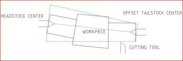
Randy, I was referring to Jim's idea of offsetting the centre on the part, mimicking that by offsetting the centre at the driven end. I think if you offset the tailstock your features will be tapered.
But just thinking about it again. you could offset the tailstock, to get the angle, then correct the angle with a taper attachment in the opposite direction to turn a cylinder.
Its late, but, I think that second approach would work.

Greg
 
Thanks for explaining your thinking, Greg.

With respect, that sounds complicated and unnecessary - just my personal opinion of course. The OP has no taper attachment and I think that he posted that making one is not in his immediate future.

This is a VERY interesting problem, we all agree on that, LOL ! I'm looking forward to see how he solves this problem -
 
Greg, re-thinking your suggestion, I'm beginning to see what you're suggesting and the geometry makes sense. I apologize - to Wreck-Wreck and others - my suggestion wasn't a good one and Greg pointed out the problem.

Please ignore my previous post :)

I modified my original sketch to understand what you were saying:

offset_zpsmci7rsfw.jpg
 
Last edited:
Is the shoulder of the block square with the axis of each spindle? I have done more than I care to think about of manufacturing "bent" parts. Forget the taper attachment. All surfaces appear to be straight turned. There is a way to do what you want that is relatively simple. You will need a 4 jaw chuck if at all possible, and a mill to build a minor bit of tooling.
 
I think you've got a good idea there Jim (reply #20). If the part is to be 12" finished length, then I would start with 15" or longer stock. Machine the stock to a precise known length, calculate the location of, and machine the centers for the two axes in each end. Turn both stubs complete (I still don't understand what the OP requires in the way of "tapered threads") leaving the extra 'blocks' at the end of the part until otherwise finished.
 
Ok I did think of a way it could be done on a manuel machine but would take a long time. With the square stock over size enough. mill the 2 deg angle in the center on opposite the lingth of your 4 jaw. and turn the first side. Now mill the angles 4 deg the outher way and machine the second side. Now square up the middle. Me, I would never attempet it but it could work.

A rotary transfer machine can be set up to run that part in production, and thay have been around a long time. Before that it was commin to build specialty machines to make a part like yhat
 
Are their any clues on the original piece? E.g. Center holes or random pin holes that may have been used during the manufacture process?

Stuart
 
Back
Top