Help on wiring a Rong Fu mill

Those little red wires with blue insulators power a light, they grab power off 1 leg of the 220 circuit. That’s the ONLY thing I’m sure about on this set up! Lol yes the motor has five wires coming out of it and is supposed to connect to the reversing switch. But at this time they are just hanging down, not connectEd at all. That is were my problem lays, what wire to put where on the reversing switch. I will get more pictures, today. The reversing switch is kinda straight forward, as the center three terminals receive power, that is ground/neutral and the the two power legs on the bottom two terminals. The the top and next to the top of the center terminals are connected by what looks like a factory connecter. Then when you turn the switch one way, it connects all the center terminals to right side terminals. If you turn it the other way it connects to the left side terminals. One question I have is what are the littke factory wires that seem to connect the left side with the right side? Are they resister wires or diodes? I think I can see something in the diagrams that indicates they are something like that. Any help will be appreciated.


The way the motor is wired now , to me does follow, either diagram in the motor cover. I cannot prove that that junction box cover lid is original to the motor... it looks like it is. But it only shows four wires..... but six wires come out of the motor, into the box and five wires leave the box. But I do not know it that is right or necessary. I bought this mill this way, so I have no history as to why it is like this.


Bones
 
Last edited:
Yes you should have 4 wires plus ground leaving the motor junction box- yet the switch diagram shows 5 wires coming in from the motor so that is a puzzle for sure- let me study that for a bit and get back to you. Those little factory jumper wires you mentioned are supposed to swap the polarity of either the motor run winding or the start leg to reverse the motor.
Looks like somebody took the motor off to move the machine and didn't mark the wires- it happens
Mark
 
Let’s hope that is what happened! I was out in the shop today, but forgot to take my iPad for better pictures! Will get some tomorrow! Thanks for your help, I’m pertty good with 12vdc, but this AC stuff, just boggles my mind! And every time I get involved with it.... the numbers don’t match, for some reason! I can put a round peg in a round hole..... but when they give you a square peg and a star shaped hole and 4 pegs and six holes!! I’m lost! Lol


Bones
 
We should be able to figure it out- do you have a multimeter of some kind?
 
Yep, i do! But I don’t know what to test. For some reason AC current blow my mind! lol
 
OK, first thing is that diagram in the switch cover is one of the worst I've seen as far as clarity. I think what I'll do is redraw it for you.
Give me a little time and I'll post it here. Go ahead and shoot a couple more pictures of both the switch and the motor side box. Also, tell me the voltage rating on the start capacitor; we may want to do a wiring change at the motor side.
M
 
Last edited:
I'm going to have you make a couple changes to the factory wiring. Two things are of concern:
1) For the single phase hookup, the switch doesn't break both line wires when in the "off" position. Personally, it's not a big deal since you wouldn't be messing with the wiring with the unit is plugged in (would you?) but a lot of folks prefer to have both line wires interrupted, if possible.
2) When a dual-voltage motor like yours is configured for 240 volts, the start circuit is usually arranged so that the start capacitor only sees 1/2 of the supply voltage. Currently the factory diagram shows the start capacitor would receive the full 240 volt which will probably shorten it's life. This is why I asked about the cap voltage rating.
We can fix both of those things and simplify the wiring too. Stay tuned.
M
 
Try this:
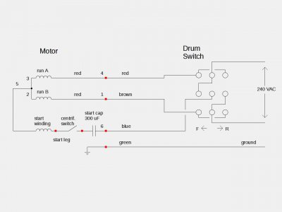
At the motor, disconnect wire 5 from the terminal strip and connect to 2 and 3 and insulate. You can use the bottom position on the terminal strip to do this since the black wire is not used. You can leave it there and tape it or strip it out- your choice.
At the drum switch you need to move and add a couple more jumpers, and reconnect the 240 volt power as shown.
Rongnew1a.jpeg
 
Make sure the switch cover can go on without touching any terminals- a strip of mylar inside wouldn't be a bad idea
And do something about that dangling cap, too :)
 
Back
Top