Wiring a Drum Switch on Logan 820 lathe
I don’t pretend to know a lot about electricity but I have done a fair amount of home wiring and I have studied several YouTube videos on my problem and I still am stumped. I need your help.
In replacing the old motor on my 1947 Logan lathe, the motor on the machine did not have a drum switch and the old motor had a built-in forward reverse switch on the motor itself. Very inconvenient and the motor was a bit undersized at 1/3 hp.
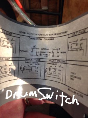
I had a 1970s Craftsman 1hp motor that had not seen much use so I have decided to use that motor as the replacement. (I know this motor is a bit overpowered but I have it on hand). I ordered a drum switch from eBay and it was for single phase, 115 or 230 volt motors. The configuration of the switch is in a picture below.
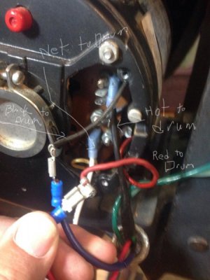
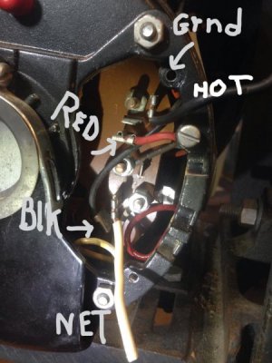
On the motor housing it states that to change rotation of the motor you switch the red and black leads. A picture of the electrical connections are below as the motor was first opened up (I had cut the hot and neutral wires and removed the ground wire for the picture). The black and red leads are visible in the picture and use female spade connectors. (In my amateur opinion it looks like the male spade connectors on the circuit block are for connecting the red and black leads to the hot and neutral poles and the red and black wires run back into the motor to the starter windings)
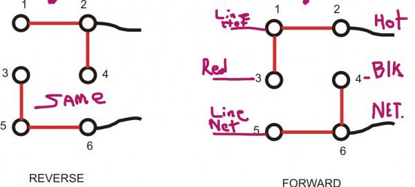
I wired the motor up as seemed logical from looking at YouTube and drawings and the wiring at the motor looked like the third picture below (again without ground) and the switch was wired as the diagram below shows (again ground omitted).
Here is where I am stumped…the motor works at this point using the switch and will change direction but it is not sounding at all like the correct hookup and makes quite a racket. I did not run the motor for long and wanted to double check the correct sound so I put the original wires back on and the motor again runs smoothly and quietly in both directions when I change the red and black leads.
Needless to say I went back to the drawings, tried different configurations and nothing else worked. The only thing that seems to work but defeats the purpose of the switch is to bring four wires from the motor into the drum switch representing both ends the male and female ends of both the red and black wires and using a separate single pole switch for the line power wires. Runs smoothly with that but obviously isn’t right.
I am thinking one of you may have had this problem and might offer a few suggestions. I don’t have much hair left as it is and pulling it out has not solved the problem. Thanks for any suggestions you have.
Ops, if this is in the wrong place, of course move it where you think is best suited.
John from Minnesota
Pictures may be out of order, fat fingered...
I don’t pretend to know a lot about electricity but I have done a fair amount of home wiring and I have studied several YouTube videos on my problem and I still am stumped. I need your help.
In replacing the old motor on my 1947 Logan lathe, the motor on the machine did not have a drum switch and the old motor had a built-in forward reverse switch on the motor itself. Very inconvenient and the motor was a bit undersized at 1/3 hp.
I had a 1970s Craftsman 1hp motor that had not seen much use so I have decided to use that motor as the replacement. (I know this motor is a bit overpowered but I have it on hand). I ordered a drum switch from eBay and it was for single phase, 115 or 230 volt motors. The configuration of the switch is in a picture below.
On the motor housing it states that to change rotation of the motor you switch the red and black leads. A picture of the electrical connections are below as the motor was first opened up (I had cut the hot and neutral wires and removed the ground wire for the picture). The black and red leads are visible in the picture and use female spade connectors. (In my amateur opinion it looks like the male spade connectors on the circuit block are for connecting the red and black leads to the hot and neutral poles and the red and black wires run back into the motor to the starter windings)
I wired the motor up as seemed logical from looking at YouTube and drawings and the wiring at the motor looked like the third picture below (again without ground) and the switch was wired as the diagram below shows (again ground omitted).
Here is where I am stumped…the motor works at this point using the switch and will change direction but it is not sounding at all like the correct hookup and makes quite a racket. I did not run the motor for long and wanted to double check the correct sound so I put the original wires back on and the motor again runs smoothly and quietly in both directions when I change the red and black leads.
Needless to say I went back to the drawings, tried different configurations and nothing else worked. The only thing that seems to work but defeats the purpose of the switch is to bring four wires from the motor into the drum switch representing both ends the male and female ends of both the red and black wires and using a separate single pole switch for the line power wires. Runs smoothly with that but obviously isn’t right.
I am thinking one of you may have had this problem and might offer a few suggestions. I don’t have much hair left as it is and pulling it out has not solved the problem. Thanks for any suggestions you have.
Ops, if this is in the wrong place, of course move it where you think is best suited.
John from Minnesota
Pictures may be out of order, fat fingered...