- Joined
- Apr 30, 2015
- Messages
- 11,291

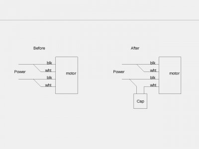
It would be wired in series with either the wire from the centrifugal switch or the one from the start winding (both look like light colored fabric covered wires in post #1)
Polarity doesn't matter
So, one of those two wires goes to one post of the cap, the other post of the cap goes to power. If in fact this is a capacitor start motor.
-M
You mentioned in post #1 that the motor was working, if so why did you assume a cap was required/missing? Was the motor starting sluggishly?
Looking at post #5, it looks to me (if that's the factory wiring, and it may not be) it would be a tight squeeze to stuff a cap in there
You could wire in the cap and try it out, it may start a bit faster. I don't think you can damage anything.
Troubleshooting sometimes takes a bit of back and forth, personally I don't mind spending the time if I can help someone out
-Mark
Unfortunately the meter works fine, on 200 and 2000 it reads the 35 ohm resistor perfectly. I am at a loss, when I bought this grinder I did test it, the mag chuck and the motor worked. Then somehow in travel it stopped working when I got home and tested it the mag chuck no longer held. I did a post about it and showed the wiring, it was all pretty bad.OK now I think we are getting somewhere. The bridge rectifier was miswired and might be damaged now.
The negative terminal is on the diagonally opposite corner from the plus. The AC terminals often have a sideways "S" which is a symbol for a sine wave.
Secondly, your chuck coil may be bad or your meter is giving odd readings. Does the meter zero when you short the test leads? Try measuring the 35 ohm resistor on the 200 ohm and 2000 ohm scales to check it.
We can also test your bridge if the meter is ok, but if the chuck coil is bad you have bigger fish to fry
-M
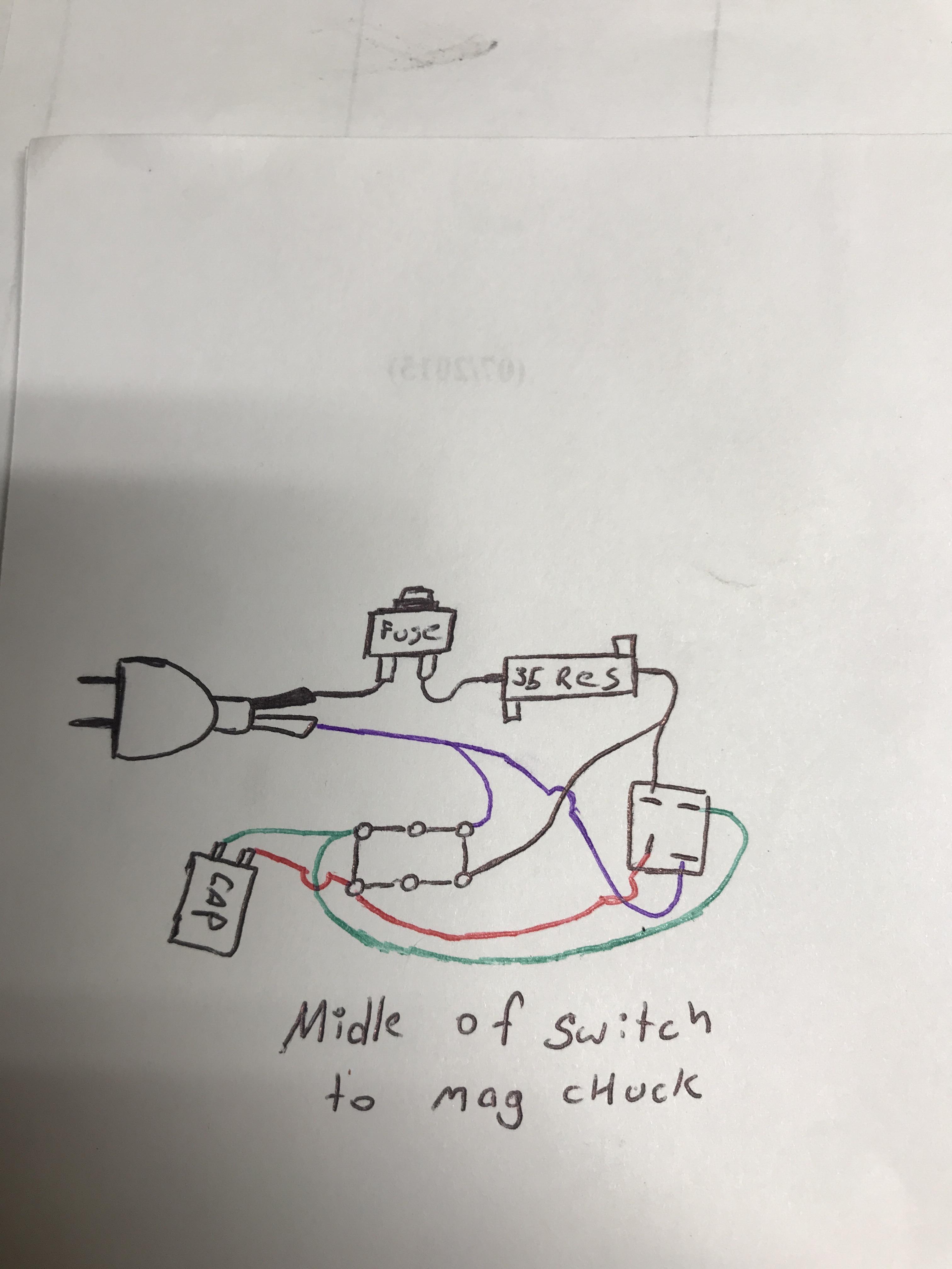
Ok, does that circuit look better than the first one? I was going to feed the motor switch straight from the + and - and not from the switch, since the resistor is feeding the power to the first switch. I think I wired in the cap right, it had a gray line down the side with an - in it, so I thought that was the negative side.OK well it may be that the chuck is partially open circuit but it sounds like it's working, or trying to.
Did you observe the polarity of the cap? Some caps have one lead marked with a plus and some with a minus. Make sure it's correct, or the cap may explode or leak.
You could try eliminating the 35 ohm resistor- that would be the chuck's maximum force- it won't get any better.