Help with motor wiring

jcp

H-M Supporter - Sustaining Member
H-M Platinum Supporter
Joined
Nov 29, 2017
Messages
530
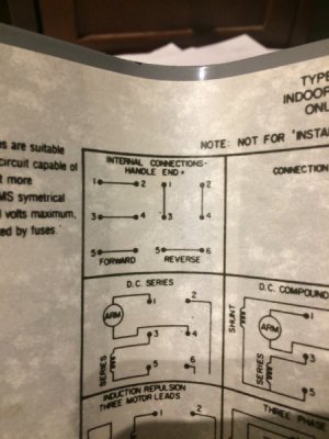
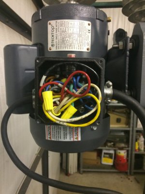
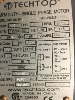
I’m trying to wire a 3/4 hp motor for 110 v to drum switch for my mill. I’ve searched and found several threads but can’t convince myself that my motor/switch combination is the same as discussed. I’m attaching pictures of my motor plate and switch. Any help greatly appreciated. I’m totally out of my element.
A159DD08-0157-450C-A107-9D0B0F028ACC.jpegE39427E4-E1A8-48EF-A4A6-E2E2FB14CD65.jpeg
 
Looks like this is what you're looking for. I suggest calling the number on the diagram to confirm since it doesn't state low voltage, but it seems to match up to your motor using the correct leads/connections for 110 volts.

Ted
 

Attachments

  • TTI RD1 DRUM SWITCH DIAGRAM v1.pdf
    583.4 KB · Views: 30
Thanks for the help. Appears to be correct to me also. I Googled 'drum switch' and 'Techtop' and didn't come up with this. How did you find it?
 
I actually just received it from a TechTop applications engineer two days ago! I just picked up a Jet milling machine which had a bad motor and switch for a song... The 1-1/2 HP motor I bought from Surplus Center had 7 leads instead of the normal 6 for a duel voltage single phase motor. Also, the Dayton drum switch I got was the other style with the L shaped contact configuration. These TechTop motors with thermal overloads have a dual element thermal device that protects both the run and start windings separately. Nice feature until you want to hook one up to a drum reversing switch. What do you do with the extra lead of P2 when wiring for 220 volt??? Anyways, the engineer sent me that drawing first and I ended up calling him saying he gave me a diagram for 110 not 220. Low voltage has the run windings in parallel and high voltage has them in series. If I had used his drawing it would have burned out my windings! Good thing I drew it out and check it. Anyways, about 45 minutes later he called me back and sent me an email with a picture of a hand written pin out for the wiring. The only way he could make it work was to have the motor run windings hot (not energized, just potential voltage) even when the switch is in the off position (the windings are not energized since only one end of them is connected to voltage when the switch is off, but they are each hot to ground). OK for my application, just remember to disconnect from power before working on the motor, which I would do anyways.

Anyways, that was a long story, but hey you got a drawing out of it! :)

Merry Christmas,
Ted
 
LOL!! Quite a story!!
Thanks again.
 
Looks correct to me also. Make L1 be the black hot line wire and L2 the white neutral, that way the hot is broken at the switch when in the center off position. Otherwise, if wired the other way the motor would always be "hot" with the switch off- It would still function correctly, but some folks feel that's not as safe. Even so, you wouldn't want to work on the motor or wiring without turning off the breaker anyway so it's kind of moot.
Mark S.
ps Ted is correct, if you were wiring for 220v with that type switch there's no way to break both hot line wires when in off position, for some that's a big deal.
 
Last edited:
Just a follow up post. I used the schematic and it works properly. Did have to change T5 and T8 for proper rotation direction. Also it takes 6 conductors (including the ground) to hook this up. Pretty well packs the motor make up box.


IMG_0466.JPG
 
Back
Top