- Joined
- May 23, 2020
- Messages
- 15
The spindle drive on my CNC mill recently died. I asked Syil for a replacement, but of course they no longer carry them. I debated finding a new drive, but after some searching, it appears it would be cheaper to replace the drive with a VFD (I happened to have a Fuji Frenic Mini lying around) and put a new, 3-phase inverter duty motor on the spindle unless I went with an import drive from Alibaba. As I’m digging into this anyways, I decided to go the VFD route as it will be more robust for future.
I’m waiting for the motor to arrive, but decided to start digging into the wiring to get it ready. I’ll openly admit I’m more of a mechanical guy, so forgive the ignorance of my questions.
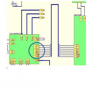
The machine is running on Mach3 through a parallel port. I’m using the original Syil Control board. An excerpt from the schematic in the manual is shown below with the outputs from the spindle drive connection to the spindle drive circled.

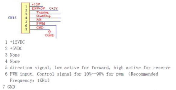
To run the VFD, I need a 0-10V single for speed control and a forward/reverse which can be a high/low, and figured I would be able to re-purpose the original connection.
I started poking around with a multimeter, and there are a couple things that don’t make sense.

Note the previous drive did work, but it behaved erratically (i.e. slowing down mid cut). Sometimes it did not start on command. I noticed a few bulges in the capacitor bank, so I assumed it was just a problem with the power being supplied to the motor, but admittedly I didn’t do any more diagnostics before pulling it off.
My key question is really whether I’m completely ignorant and going about this wrong, or if there appears to be something funky in the outputs from the control board. Thanks for any help!
I’m waiting for the motor to arrive, but decided to start digging into the wiring to get it ready. I’ll openly admit I’m more of a mechanical guy, so forgive the ignorance of my questions.
The machine is running on Mach3 through a parallel port. I’m using the original Syil Control board. An excerpt from the schematic in the manual is shown below with the outputs from the spindle drive connection to the spindle drive circled.

To run the VFD, I need a 0-10V single for speed control and a forward/reverse which can be a high/low, and figured I would be able to re-purpose the original connection.
I started poking around with a multimeter, and there are a couple things that don’t make sense.
- It appears the PWM signal is reversed. When reading with a multimeter, it is at ~18V DC with the spindle off. It drops to ~2.5 VDC at 3500 RPM (this is machine max). I would have expected this to go from low (~0V) at 0 RPM to high (~10V) at 3500 RPM.
- The 12V pin is actually 18V, but I suspect that has to do with the transformer output to the control board being a little high
- The F/R pin does not appear to go high/low. I expected it to read 0 or 5 between the pin and ground based on forward or reverse, but it just reads 0. It also reads 0 to the 12V pin. Admittedly, I don’t recall needing to run the machine in reverse with the old drive, so I don’t know if there is a problem with the hardware or a user error.
- STOP and fout don’t appear to change state. They stay 0VDC relative to ground.

Note the previous drive did work, but it behaved erratically (i.e. slowing down mid cut). Sometimes it did not start on command. I noticed a few bulges in the capacitor bank, so I assumed it was just a problem with the power being supplied to the motor, but admittedly I didn’t do any more diagnostics before pulling it off.
My key question is really whether I’m completely ignorant and going about this wrong, or if there appears to be something funky in the outputs from the control board. Thanks for any help!

