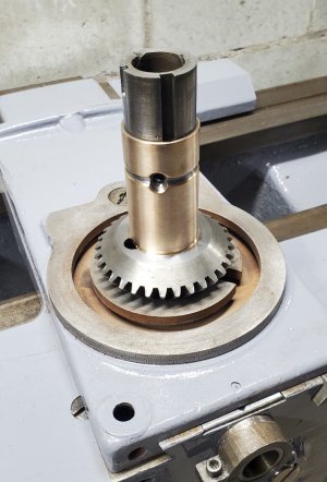
Hendey Lathe Refurbish

I didn't finish the apron this morning... I've decided to replace some of the brass oiling tubes while I have it apart, so I'm waiting on a package from McMaster with some brass tubing and a few other odds and ends in it.

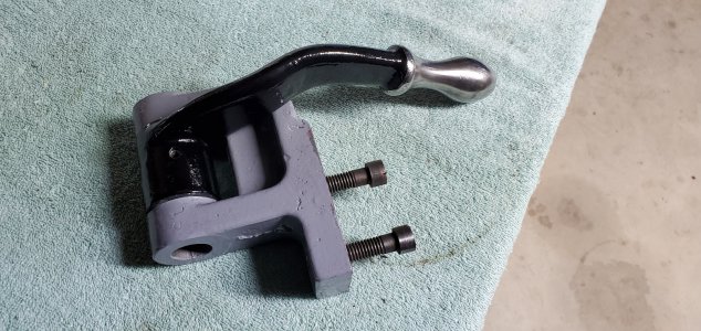
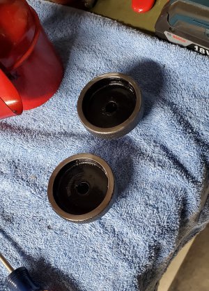
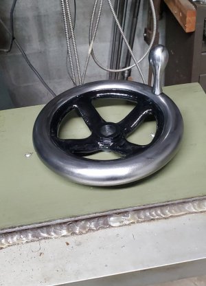
I did finish painting some of the handles and knobs, though...
20201222_125015.jpg

20201222_125049.jpg

20201222_125115.jpg

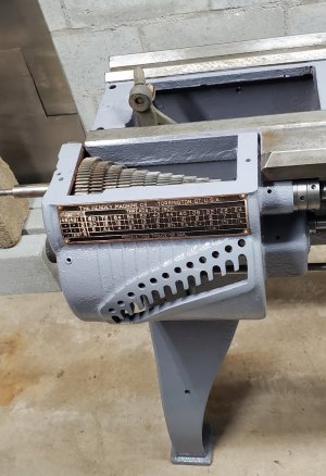
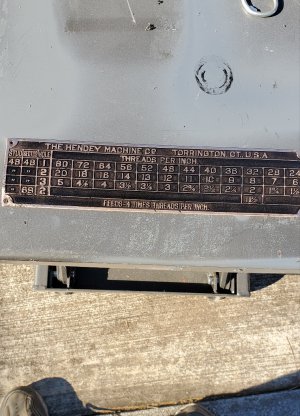
And I finished the brass threading plate...
20201222_124945.jpg

I had beadblasted the plate to remove all the old paint, then sprayed it with 2 thin coats of flat black paint. After letting it dry for a few days, I took a stone and polished the paint off the letters/numbers and grid lines. I then sprayed the plate with clear gloss. I really didn't expect it to turn out like I wanted, but I figured if it didn't, I would bead blast it again and try something different. It turned out ok, though, so I think I'll call it good...

-Bear
 
Very nice looking results! Even the data plate looks crisp. OK, not absolutely perfect ... but very nearly so.
 
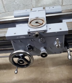
This morning, I came home from work and finished up with the apron...

20201223_150053.jpg

I managed to get it installed by myself by lifting it in place with my HF hydraulic cart.

20201223_150136.jpg

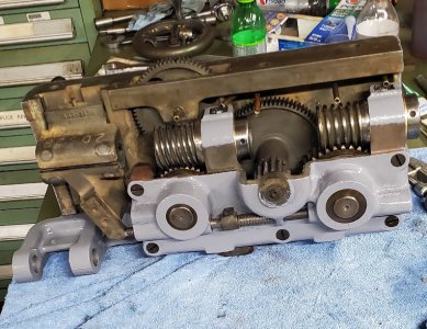
Next, I mounted all 3 of the horizontal shafts, then bolted the gearbox housing to the bed. That wasn't easy, I really needed some help, but managed it alone... I tried to use the HF cart, but it would hit the front of the lathe leg before the gearbox was close enough to the bed to start the bolts. I finally managed it, though.

I assembled the main gear assembly inside the gearbox after bolting it to the bed. Getting all the gears in place was... difficult...
I finally took them all back out and marked the tooth directly above the key seat on each gear to help me line the key seats up with the key on the lead screw.

20201223_150204.jpg

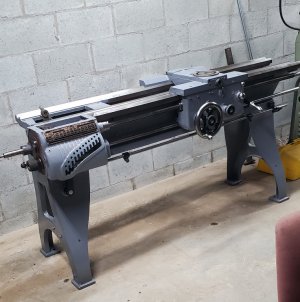
It's starting to look pretty nice, I think...

20201223_150226.jpg

Next, I guess I will tackle the headstock... I'm a little intimidated by that part of this project. I guess I'll just dive in and do it... tomorrow, maybe.

-Bear
 
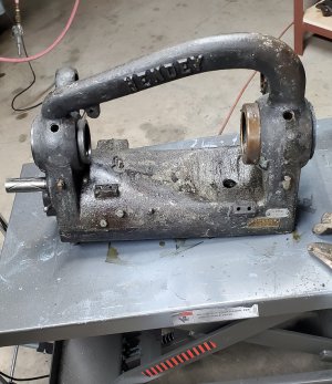
Well... I pretty much have the headstock apart...

20201224_145227.jpg

The headstock bearings are both made of a babbit type material. They are in pretty good condition, with a tiny bit of very minor scoring in a spot or two... I don't think it is going to be a problem.

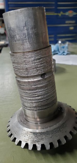
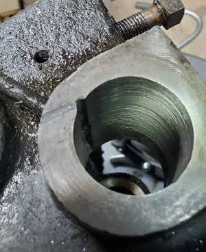
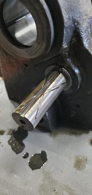
However, I did find a problem... when I removed the feed reversing clutch assembly, the clutch input shaft is badly worn, as is the bore in the headstock casting that it rides in.

20201224_144916.jpg

20201224_144750.jpg

The shaft turns smoothly in the bore, and there is very minimal side play between them, but this is something that I will have to address...

I'm thinking maybe turning the shaft and press fitting a bronze sleeve on the shaft, then boring the hole to clean up, and machining the sleeve to fit the hole...

I know the issue will be re-establishing the oiling grooves on the OD of the sleeve... they won't be very deep, but I should be able to get them to work.

Any thoughts, advice, or other ideas on this?

-Bear
 
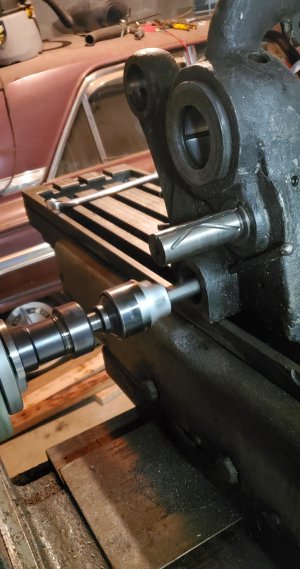
After spending about 2 hours setting the headstock up on the horizontal mill, I managed to get it within .001"... I actually indicated the shaft above the clutch bore, then checked the clutch bore at the end and as deep as the indicator would reach...

20201224_183309.jpg

I then went ahead and set up a boring head and bored the hole to clean up plus .010". That gives me a .040 overbore... it should be ok.

20201224_183358.jpg

I hope...

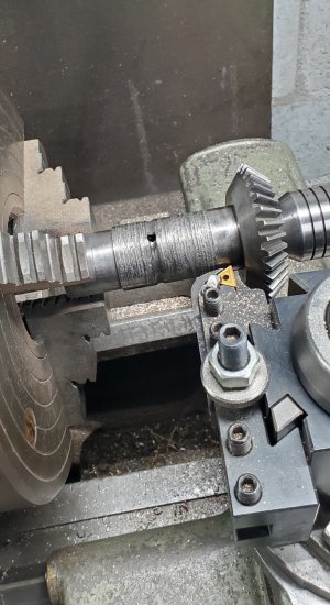
I also have the clutch shaft mounted and indicated in the lathe...

20201224_184014.jpg

I'll turn it in the morning...

-Bear
 
This morning I skimmed the OD of the shaft, then bored out a piece of bronze to be a press fit over the shaft. I pressed it on with the arbor press, then set it back on the lathe and turned the OD of the bronze for a .003" clearance fit in the headstock bore.

After machining the oil supply groove and re-establishing the holes that supply oil to the clutch output shaft, this is what it looks like...

20201225_111953.jpg

I think this should last a long time. I believe the reason it wore so badly was because the tube that supplies oil to this bore was clogged with jellied oil mixed with other gunk. After I get it all cleaned out, maybe it will go another hundred years or so...

-Bear
 
The last couple of days, I've been working toward creating a plan to clean the inside of the headstock casting...

There are 2 oil reservoirs in the casting, one under each of the spindle bearings. These reservoirs hold the spindle oil... there is an oiling ring that runs in a groove in the bearings that picks up the oil and carries it up to the top of the spindle, where it deposits the oil and lubricates the bearing. Both of these reservoirs are completely filled with jellied oil that has to be removed.

To gain access to these reservoirs, the spindle bearings need to be removed from the casting, but, from what I am reading, when they are driven out of the casting, they normally break and come out in pieces. I really don't want to deal with having to machine new bearings if I don't absolutely have to.

The outboard (small bearing) reservoir can also be accessed by removing this fixed shaft from the left end of the casting...

20201229_082708.jpg

I am planning to attempt to get it out, but will have to machine a tool to remove it... shouldn't be a problem. That should allow me to clean out the small reservoir.

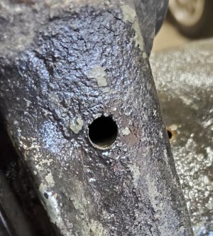
The inboard (large bearing) reservoir is a different story, however. The only other access to it is through a 5/16" oiler hole in the front of the casting...

20201229_082556.jpg

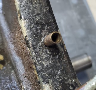
And a ¼" drain tube in the rear of the casting...

20201229_082520.jpg

IOWs, there is not much access to that reservoir...

So, taking into consideration that the drain tube on that reservoir has been previously damaged and needs replacing anyway, and considering that the tube is brazed into the casting and probably impossible to remove without drilling it out anyway, I formulated a plan...

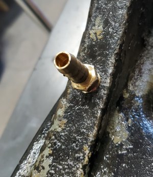
I cut the tube off flush with a hacksaw, then step drilled the hole out all the way into the reservoir and tapped it with a ¼ NPT tap. I then threaded a hose barb into the hole...

20201229_082634.jpg

I set the entire casting into my parts cleaning tank and plumbed the output line from the circulating pump directly to the hose barb. I turned it on yesterday morning and left it running for 22 hours... this morning I removed the hose to check the progress... it looks, (from what I can see) to be extremely clean inside! I was actually surprised at how clean it looks.

When I get it all back together, I will drill a hole through a ¼ NPT plug, machine a new drain tube, and braze the tube in the hole in the plug, and thread it back in place of the tube that I drilled out.

Thats the plan I'm going with at the moment, anyway. I don't really like making alterations like that, it seems too much of a 'hack job' to me, but I needed some way of flushing the reservoir and had to replace the damaged tube somehow, so that is what I decided to do.

-Bear
 
Back
Top