Hendey Lathe Refurbish

I haven't accomplished a lot on the Hendey this week. I've been attempting to formulate a plan on where and how to do the electrical controls and wiring.

I finally realized that I need to finish up with all of the pulleys and install the belts so that I can plan the electrics around the drive system... it wouldn't be a good idea to get a switch too close to a belt or pulley.

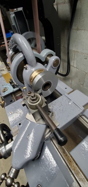
I started with the flat belt pulley... I had found and purchased one from ebay. The center bore on the pulley is 1 ⅛"... the output shaft of the transmission is 1", so I machined a sleeve for the pulley, epoxied it in place, then finish bored it and re-established the keyway...
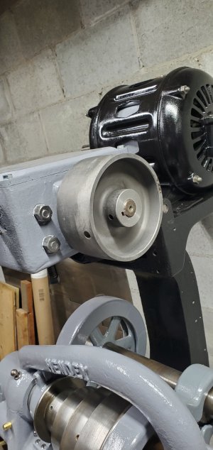
20210219_162022.jpg

I measured and ordered a 57" belt from a seller on ebay... it should arrive next week.

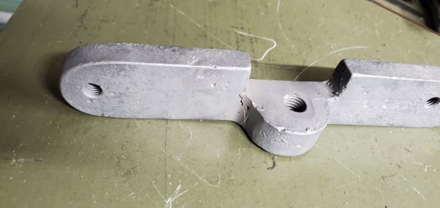
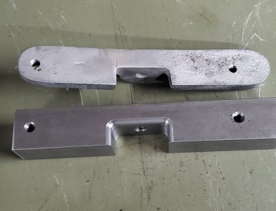
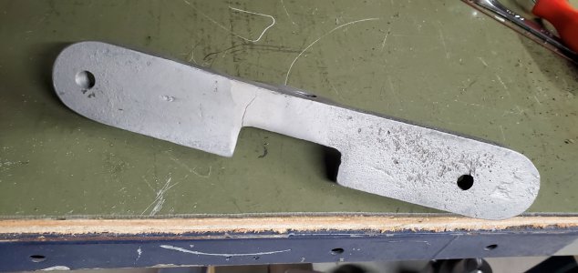
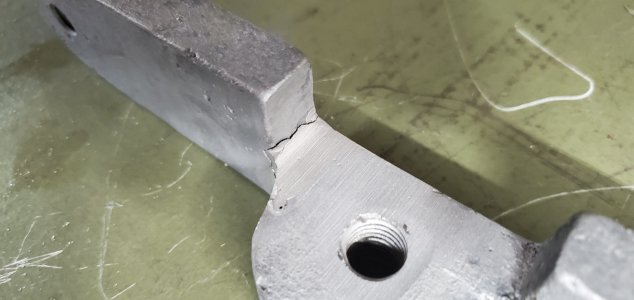
I've cleaned both flat belt pulleys... I was going to go ahead and install them, then bolt the motor to the belt adjustment slides and measure for the v-belts and go ahead and order them today, but found a problem... one of the adjustment slides is cracked... almost broken...
20210219_162217.jpg

20210219_162240.jpg

20210219_162235.jpg

It has already been repaired once and has cracked again in the middle of the repair. I don't know what was used to repair it, it looks like brazing, but it is gray, maybe aluminum bronze? I don't really think repairing it again will be an option, so I'll just make a new one.

-Bear
 
I machined a new motor mount slide from a piece of 1-½" square steel bar...

20210226_145101.jpg

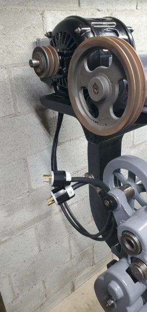
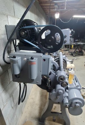
I started wiring the motor... I wired in a homemade 'pigtail'... I connected the 6 wires coming from the motor windings to 2 lengths of electric wiring. One has 4 conductors, the other has 3... the extra conductor I used as a ground from the motor case. I connected the other ends of the wires to 2 twist lock type plugs. I decided to add the plugs in the system so if I ever need to remove the motor I can just unplug it from the controls rather than having to unwire it...

20210226_145628.jpg

I have the female half of the plugs, which will be mounted in the motor control panel...

I bolted the motor to the bracket and installed the pulleys to measure for belt length. I need 5/8" wide by 44" long belts. I ordered 2, they should be here in a couple of days.

-Bear
 
I've been tied up working on other things for a few days, but I do have most of the controls wired up, I still have to finish wiring the on/off switch and the wire that goes to the 3 phase system. I'll try to finish that later this week.

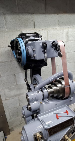
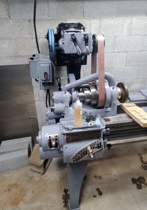
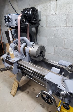
I have installed both v-belts and the flat belt...

20210304_162539.jpg

... and found another problem.

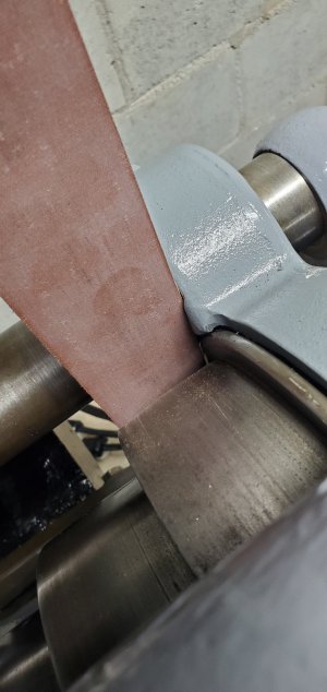
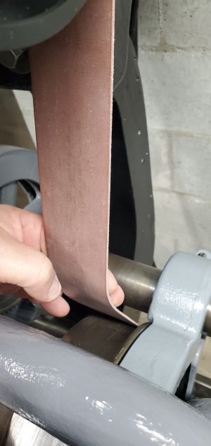
The flat belt is running against the bull gear guard...

20210308_151305.jpg

The original belt apparently had been rubbing the guard also. There is a groove (either worn or machined) in the guard, but it still doesn't clear the belt.

I've come up with two options for fixing this... either grind more off of the guard, or fabricate an idler pulley and bracket that will hold the belt away from the guard...

20210308_151513.jpg

...by pulling the belt forward.

I'm leaning toward using an idler pulley... that would make tensioning the flat belt and v-belts easier.

Previously, I had mentioned an issue with tensioning the belts... the transmission hinges on a shaft at the back, which means as you loosen the flat belt, the v-belts tighten, and vise-versa... now I'm realizing there is another issue with this setup.

When I try to tension the v-belts, they will actually lift the front of the transmission off the flat belt adjuster before they are tensioned. I'll have to wait until I can get everything spinning and see how serious an issue this will be. It may work fine, or the belts may slip... IDK yet.

-Bear
 
WOOHOO! IT'S ALIVE!

I finished the wiring this afternoon... then put all of the belts back on and tightened them. It works smooth and quite in forward, reverse, high speed, low speed, and all gears...

However, I couldn't get the feeds to work. When I would engage the feed reversing clutch, it would stall and the flat belt would slip. I worked with it a while, looking for problems and finally discovered 2 gears that were binding... the one on the reversing clutch output shaft was binding on the gear that drives the small gearbox... a quick and simple adjustment solved the issue.

This is how I set up the motor controls...

20210309_190433.jpg


20210309_190443.jpg

I mounted both drum switches and the start/stop switch on an electrical enclosure box and hung it from the left side of the motor support bracket. All of the wiring is inside the box... the box also has the twist-lock receptacles for the motor plugs mounted in the bottom.

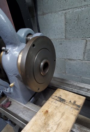
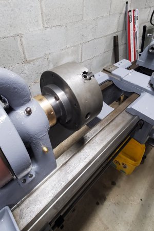
I was going to chuck up a piece of aluminum and make a few chips, but discovered that I have an issue with the chuck that came with the lathe. The backplate fits the spindle with less than .001" runout on the face and register diameter, but the spindle is longer than the backplate is thick...

20210309_190022.jpg

The problem is that the hole in the back of the chuck is smaller than the spindle diameter, so it won't thread all the way to the shoulder on the spindle.

So... I'll have to either fit the backplate to another chuck, or machine a new backplate for another chuck before I can use the lathe.

I'll work on that tomorrow...

-Bear
 
Great to see that you got it working !
 
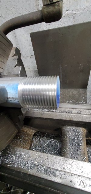
I drove over to McMaster this morning and picked up a 6" diameter by 2" thick piece of cast iron for a backplate. I started on it after lunch... but first I had to turn a threaded piece to match the spindle on the lathe. I will use it to check the threads in the backplate as I machine them... I used a piece of aluminum for the guage.

20210310_142619.jpg

It fits the old backplate pretty well.

20210310_142719.jpg

Then I chucked up the chunk of cast iron and started whittling on it... the outer scale on it was difficult to machine. I had to use the backgear on the South Bend to slow it way down to get the scale to machine. After I got past the scale, I could turn it faster.

I'm almost ready to begin threading...

20210310_180955.jpg

I still have to machine the counterbore for the spindle register and chamfer the ID... then I'll set up to chase the threads.

Maybe tomorrow...

-Bear
 
This morning I threaded the backplate... it is 2-¼ x 6 tpi. I managed to achieve a very nice fit to the spindle threads. I flipped it in the South Bend and roughed in the OD, leaving it .020" large, and faced it to clean up.

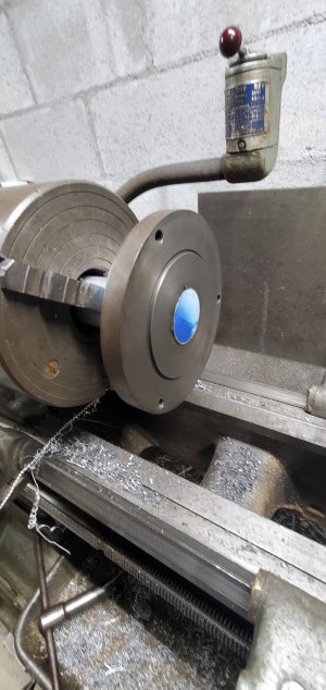
I then mounted it on the Hendey and turned the OD to size to fit the register on the back of a 9" Union 3 jaw combination chuck. I also skimmed the face to true it up...

I finally made some chips with the Hendey!

20210311_125822.jpg

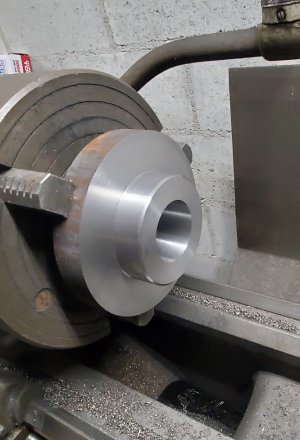
After truing it up and chamfering the edges on the Hendey, I clamped the backplate to the mill table and drilled and counterbored the bolt holes to bolt it to the chuck.

I'll call the backplate finished now.

20210311_143900.jpg

20210311_143909.jpg

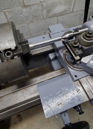
I adjusted the tailstock to center it, then chucked up a piece of aluminum and turned a 6" length...

20210311_150153.jpg

Over a 6" long cut, the diameter only changed about .0002"... that is two tenths of one thousandth! Both ends of the cut were exactly the same with the middle being .0002" larger... the aluminum may have been pushing or springing away from the tool...

Woohoo! I'm pretty impressed and excited about it!

I'll consider the lathe 'useable'... but I'm not done with it yet. The flat belt is still rubbing the bull gear guard, I'm going to make a new screw for the tailstock (I've determined that it has been shortened by 1-½"), and I have a 10" Cushman 4 jaw chuck that I am going to make a backplate for (I'll probably modify the backplate that came with the lathe to fit the 4 jaw instead of making another from scratch).

I'm happy with how it has turned out.

-Bear
 
Back
Top