Hendey Refurbish #3

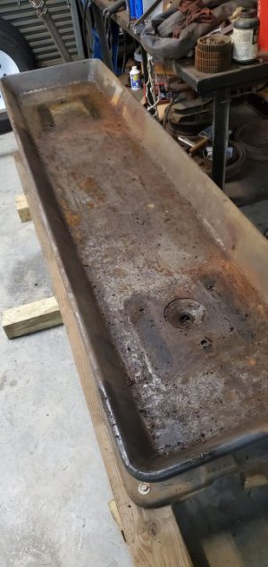
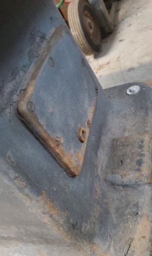
This afternoon I spent some time scraping crud out of the chip pan... under the right hand riser I discovered an oil drain that was covered with 1/4 inch of crud...20220303_162254.jpg
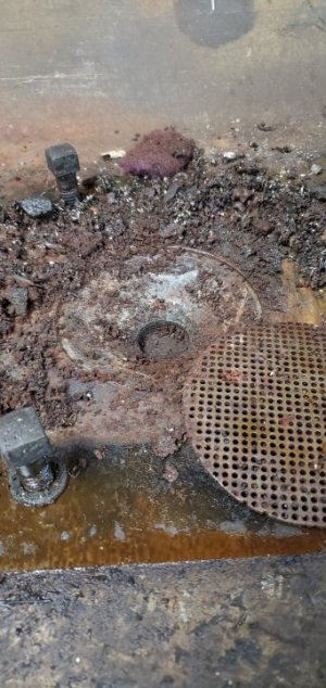
It drains into a sump in the right leg, and there is a plug in the side of the leg to drain it...
20220303_162300.jpg

I finished scraping out the pan...

20220303_163910.jpg

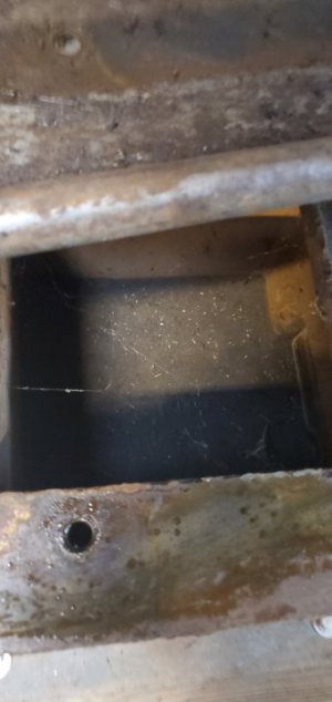
...and then my curiosity won, and I had to take the pan off to see what was in the sump. I was hoping it would be packed with 100 dollar bills... but it was empty...
20220303_163926.jpg

...except for a few cobwebs. Oh, well...

-Bear
 
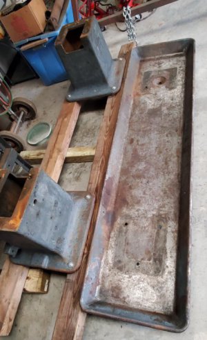
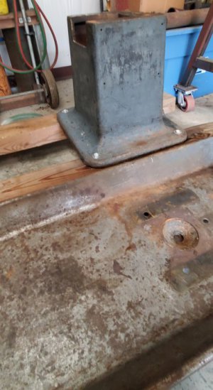
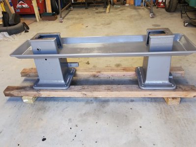
Yesterday I degreased and pressure washed the chip pan and legs...

20220308_094817.jpg

20220308_094834.jpg

It's in my shop drying out.

Tonight will be my 18th night straight at work... then I'm going to take the rest of the week off. I was hoping to get the pan and legs prepped and painted while I'm off, but it's supposed to rain the rest of the week, so I probably won't get any painting done. Maybe next week...

-Bear
 
Back in post #1, I mentioned that the lower clamp bar that connects the taper attachment to the cross slide screw had the end broken off... I began looking at it this morning to begin planning a repair...

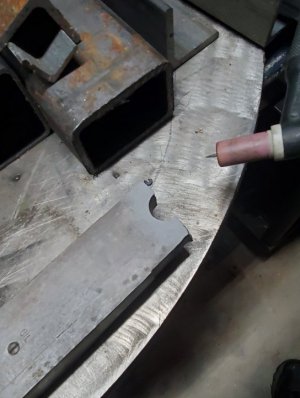
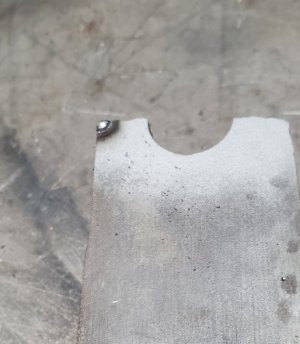
The first thing was to determine what material it was made from... I was pretty sure it was cast iron, but was hoping it was steel. I first degreased and cleaned it, then sandblasted the broken end to get to clean metal...

20220309_104945.jpg

...then fired up the TIG welder and did an arc test on it...

20220309_105308.jpg

It is definately cast iron. That may complicate things... I've not had a lot of luck welding cast iron, and I'm not sure that brazing it will be strong enough.

I'm debating whether to cut the end off and bolt a piece of steel to it to machine back to the original shape, or to order a 2x2x12" steel bar and attempt to machine the entire piece...

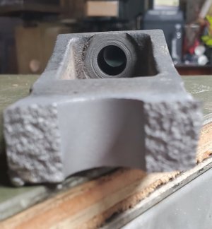
If I machine a new piece, this counterbore...

20220309_112502.jpg

... is going to be tricky without a back spotface setup... it's doable, but tricky.

I'll likely attempt to just replace the broken end... if that doesn't work, then I'll go to plan 'B'...

-Bear
 
"I'm debating whether to cut the end off and bolt a piece of steel to it to machine back to the original shape, or to order a 2x2x12" steel bar and attempt to machine the entire piece..."


^^^^^^^^^^^^^^^^^

This!! :aok:
 
This afternoon I took advantage of the nice weather and put the first coat of paint on the legs and the bottom of the chip pan. I am using Massey Ferguson gray paint from Tractor Supply on this lathe... it will need at least two coats.

Also, the brown truck delivered a package...

20220314_163919.jpg

A length of 2"x2" 1018 to machine a new clamp bar out of. I couldn't come up with a way to repair the broken one that I felt comfortable with, so I decided to machine a new one.

We'll see how that works out...

-Bear
 
I began working on the new bar... I cut a piece to the approximate length and set it up on the shaper to rough the dimensions...

20220315_150550.jpg

After getting it close, I put it on my old surface grinder and cleaned up the top and bottom.

20220316_170159.jpg

I'm getting a pattern in the ground finish...

I think the spindle bearings in the surface grinder are about to give out... the spindle is noisy and I can't seem to get a good finish... it feels smooth, but definately has a pattern in it.

So... I've started looking around for another grinder... there aren't many available near me, though, and I'm not really interested in driving very far with the current gas prices.

My current grinder is an ancient Taft-Peirce #1... it is a manual grinder. I'd like to replace it with an automatic grinder.

It is my least favorite machine to run... I have it lifted 6 inches and it is still too short for me. It kills my back to operate it too long...

-Bear
 
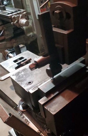
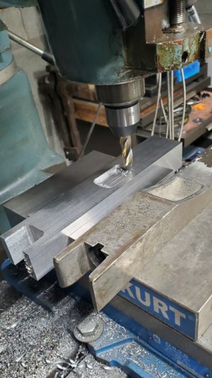
I've finished grinding the block for the clamp and began machining the features. I set it up on the vertical mill and milled the notch in one end, then began roughing out the rectangle hole in the bottom...

20220321_173231.jpg

The notch is just clearance for the cross slide nut... it simply allows for an extra inch of travel on the cross slide. The cross slide screw goes through the hole in the end of the clamp, and comes out into the rectangle hole. A thrust washer and nut retains the screw in the clamp... this is what anchors the screw. The rectangle hole provides clearance to install the washer and nut... nothing critical.

I also put a second coat of paint on the chip pan and legs, as well as the first coat on the apron casting.

-Bear
 
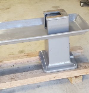
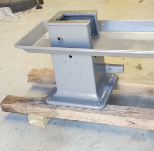
Today I finished painting the legs and chip pan...

20220323_144804.jpg

20220323_144800.jpg

20220323_144752.jpg

It turned out pretty good. Cleaning and painting the bed comes next...

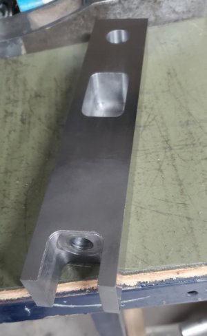
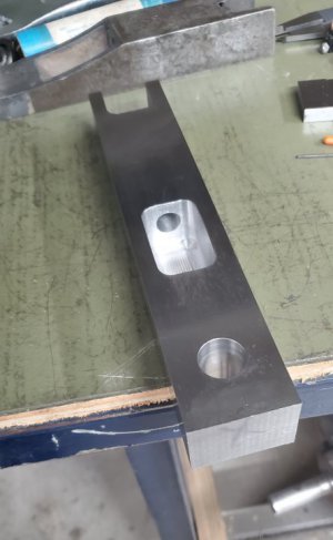
I also worked on the clamp bar some more... I finished machining out the rectangle pocket, then located and bored the 3/4" swivel hole...

20220323_152918.jpg

Then drilled a 1/2 inch hole from the notch to the pocket...

20220323_165131.jpg

20220323_165125.jpg

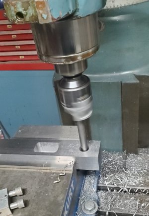
I started cutting the counterbore inside the notch, but my setup (clamped in the vise standing up on the vertical mill) wasn't rigid enough. I'll have to finish it on the horizontal mill where I can clamp it in the vise horizontally.

The original bar was cast iron... I'm making this from steel. I'll eventually bore the 1/2 inch hole out to 5/8" and install a bronze sleeve to prevent steel to steel contact between the bar and cross slide screw.

-Bear
 
One of the challenges to machining this clamp bar is trying to figure out how to machine the large radius on the bottom...

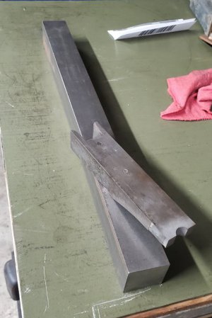
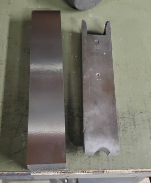
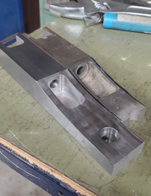
I decided to rough it on the shaper, then see how well I could finish it on the horizontal mill. First, I set it next to the broken one and used a sharpie marker to trace the radius onto the new part.

Then I set it up on the shaper and machined it... 0.050" depth of cut... until I was within the sharpie line. Back out, drop 0.050", cut again to the line...

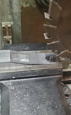
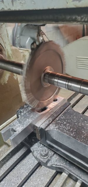
Then I set it up on the H-mill... using the largest diameter cutter I have, I machined it as close to the line as I could using my highly-calibrated eyeball...

20220324_101715.jpg

20220324_104604.jpg

I then used the curved top of my belt sander to smooth it out and polished it with a scotchbrite wheel.

20220324_110636.jpg

It turned out much better than I thought it would... I'll call it a success.

The pocket in the new piece is obviously shorter than the old one... this is because there is an angle on the front of the pocket. I still have to machine that angle, cut the two counterbores on the 1/2" hole, and radius the nose on the swivel end.

I have a NMTB 50 end mill holder ordered to use to cut the counterbore inside the notch... I still haven't figured out how to cut the counterbore inside the pocket.

-Bear
 
Back
Top