• Welcome back Guest! Did you know you can mentor other members here at H-M? If not, please check out our Relaunch of Hobby Machinist Mentoring Program!

  • In order for the Member Map to work properly, you must allow Google services AND Hobby Machinist to know your location. These settings are found in your browser of choice and in your Hobby Machinist profile.

Winner Home Grown Cutter Grinder

Status
Not open for further replies.
I can't get a clear shot of the label for some reason. This is what is on it. The only other tag is a warehouse tag with much of the same info. There is no junction box, jut three wires coming out of the case. 2 white and 1 blue.

REF SB28 550264/05B
Volts 110/120 micro Farad 20.0
Volts AC
Hz 60 Phase 1
Watts Output 100
RPM 3400
Rating Continuous
Insulation Class F
Max Ambient Temperature 40 degrees C

"Billy G"
 
According to the gent that built the first one, 1/8 HP is sufficient. Let's hope he is right. :thinking:

"Billy G"
 
I can't get a clear shot of the label for some reason. This is what is on it. The only other tag is a warehouse tag with much of the same info. There is no junction box, jut three wires coming out of the case. 2 white and 1 blue.

REF SB28 550264/05B
Volts 110/120 micro Farad 20.0
Volts AC
Hz 60 Phase 1
Watts Output 100
RPM 3400
Rating Continuous
Insulation Class F
Max Ambient Temperature 40 degrees C

"Billy G"

My best guess: connect the capacitor between the two white leads, neutral to the black, and line to one of the whites. To reverse move the line to the other white.

I'm used to old junk from the middle of the last century: GE and Dayton motors with real nameplates, diagrams, and NEMA labeling.
 
Thank you John. That's the way I have it in the diagram.

"Billy G"
 
This is an impressive build. Look forward to seeing the end product. On a side note, what happened to the thread with that engine you were building. Can't find it anywhere.
 
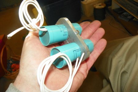
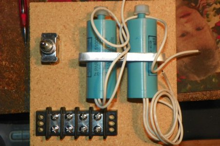
Did not wish to mount the capacitors by the studs on them so I fabricated this mount.

"Billy G"

102_0374 (800 x 531).jpg
 
The cleaner the wiring the easier it is to fix. Tomorrow the box. I am working on this early because the steel hasn't arriver yet. :))

"Billy G"

102_0375 (800 x 531).jpg
 
No Matt. I will fabricate one myself. I have a copy of Model Engineers Workshop #159. It will be like that one except for the spindle itself. Mine will have tapered roller bearings instead of Ball Bearings. As soon as the Guide Bad is finished I will start on that. That will be the slowest part. Contraption huh. :lmao::lmao::lmao

The spindle itself will come from the Workshop Practice Series #27 "Spindles" by Harprit Sandhu Chapter 13 Page 102.

"Billy G"

Bill have you looked at an air spindle, the cutter grinder we had in the shop was an air spindle it was a very smooth spindle?

Todd
 
Status
Not open for further replies.
Back
Top