

- Joined
- Aug 18, 2019
- Messages
- 10


I recently bought a cheap new 7" x 14" Chinese mini metal lathe and as I expected there were some problems with it. The one problem, which I'm sorting out in this article, is to lower the height of the tailstock centre. It's about 1mm higher than the headstock centre which is unacceptable for long turning and drilling. After a lot of thought and browsing the Internet for a solution, and finding nothing, I decided to try and skim the upper base of the tailstock myself. To do this I would need to hold the tailsock firmly on it's side on the cross slide and to use a fly cutter to do the skimming. As I don't own a fly cutter I had to make one.
Designs and videos for fly cutters are aplenty so I chose to use one of the simple ideas which I could turn on my lathe and then work out how to make the tool holder slots. I have sort-of followed the design in this drawing. I don't think the dimensions are critical.
Pay close attention, however, to the slot holding the cutting tool in place. The point of the cutter must lie along the centre line of the holder and it is crucial that you make the slot on the correct side of the centre line. If you study the images and drawing, and think of the direction of the spinning cutting tool you will see that, because of the angle of the cutting tool, it can only be on the one side.

I needed a bit of round bar about 30mm in diameter and I determined to find some scrap. Why pay for it? So I phoned a good friend who also has a similar lathe with the same faults and asked him where we could find such a bar. He said, "You know what. I have an old piece 32mm x 450mm that I brought home all the way from Western Australia, about 4000 kms". He had been on a round trip of Australia a few months back and found this thing. "I'll bet your wife asked you, 'What on earth are you taking that piece of junk back home for?' " I said to him. He laughed and yes that's exactly what she said.
So I'm showing how to turn some "fools gold" into "real gold". One person's junk is another man's treasure.


Now that this bar was in my hands I cut 3 pieces out of it using a 1.5mm metal cutting disc in my angle grinder. 2x 70mm and 1x 40mm. I'm intending to use the 2nd 70mm length to make a second fly cutter for my friend who gave me the steel rod.
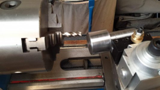
In a 3-jaw chuck turn the pieces down to remove all the rusted outside and face off the two ends.

This is the basic tool holder. I still have to mill the tool holder slots into the top at an angle of approximately 10 degrees. The tool holder head is about 25mm and the shank is about 40mm. I decided to tun the shank down to 20mm as accurately as I could as I am thinking of buying a collet set for the lathe (one day) and 20mm is a standard collet size. In the meantime I can put the 40mm shank into my 3-jaw chuck and spin the tool with that.
The length and diameter measurements are not critical but when we come to cutting the main tool holder slot it needs to be cut fairly accurately.


Being a round piece I tried to figure out how I was going to hold this in/on my cross slide/compound slide. I first had the thought that I would make a collet with square sides to clamp and hold it steady while I milled out the slots. So I turned up the collet as you can see in the pictures. The sleeve just fits over the shaft of the fly cutter and cut a slot through one of the sides. Clamping this in some sort of vise holds the cutter well - BUT there was no way I could find to support this in my quick change tool holder or on the cross slide without first making a vertical milling vise. Then I had what I thought was a brain wave...
I'm not going into detail on the making of the collet as I'm not using it for this project - it will just go into the bin for use on something else.


As my lathe tool post can hold a square bar of 8 - 10mm in it I could mount a square bar along the shank of the fly cutter. So, clamping the fly cutter shank in the 3 jaw chuck I scribed a line across its face (through the centre - this is important) and then without moving the 3 jaw chuck and marked a point on the shank of the part (so the line across the face and the mark on the shank are on the same plane). Then I turned the part around in the chuck and using the point on the shank, I scribed a line down the length of the shank. This will be the centre line to drill out the holes to support the square bar being fitted.
As I don't have a V bock in my drill press vise I had to resort to carefully measuring the distance from the line down the shank of the part across to the two jaws of the vise. This would give me a pretty good accuracy to drill the holes through the center of the shank. Having a V block would make this centre setup easy.
I carefully measured and marked the distance between the holes on both the shank and the bar using a digital caliper. As you can see from the images I drilled out the shank and the bar. The shank I drilled a 5.5mm hole for tapping a 6mm thread, and the square bar I drilled 6mm to slide the 6mm bolts through. (I wondered if I should have cut a flat surface along the shank to prevent the bar from any wobble but the bolts proved strong enough)
As you can see in the images I had to countersink the holes in the square bar and turn down the bolt head diameters to fit within the bar width (the square bar needs to fit squarely in the tool post holder without interference from these bolt heads)
When I screwed the bolts in tight the arrangement was very strong.


And here is the "gadget" holding nicely in the quick change tool post.
The angle of cut for the milling needs to be about 10 degrees so I set up the angle on my carpenters adjustable bevel. Using this I then set the tool post to the 10 degrees and clamped it down tight.
- this clamping must not be changed until the job is done.


The milling was straight forward but slow on a small lathe like this.
NB - The line I scribed across the face of the fly cutter earlier is now horizontal as it is held in the tool post. This is most important because this line is to be your reference and the main edge of the inner slot to be milled. The edge of the cutting tool should be on this centre line. Again I remind you to be careful of which side of this line you will make your slot. You can cut it on the wrong side. It will depend on whether the 10 degree angle is towards you or away from you. Picture the cutting tool in action as it spins in the chuck. If you get this wrong the cutting point cannot line up with the scribed centre line across the face of the tool. I set the angle of the 10 degrees in my case with the tool pulled in towards me (see image) and clamped the tool post down - this must remain clamped until all the milling is complete. As we are using the quick change tool post to hold the work the work, together with the quick change tool post holder can be lifted out and replaced without the 10 degree angle being changed..
Using the set up I have and using an 8mm end mill you will need to set the top edge of the end mill to run along the scribed line.
The depth of the tool holder slot will be determined by the dimension of the cutting tool you will be using. In my case I intend to use 8mm cutting tools so this slot will be 8mm wide and 8mm deep at the one end and a lot deeper at the other end (because of the 10 degree angle).
When you do the second cut (on the other side of the centre line, you will be milling away from the edge of the fly cutter to about 6mm from the first cut. This will give you a good thickness for the grub screws you'll be putting in to clamp the cutting tool. This second milling cut is also to be made a little deeper than the original 8mm cut to give space for the grub screws or if you use hex bolts instead of grub screws. This milled cut of mine was about 10mm deep.
Note: To keep chatter to a minimum I tightened up the lathe saddle plates and the gib slides on both the cross slide and the compound slide. This still allowed movement of the lathe parts but improved the cut. Oh. And if you don't have a saddle lock (something I still want to add to the lathe)( you'll need to use the lead screw clamp to stop the saddle from moving.


So when the milling cuts are done the part is removed from the lathe and the face of the second milled cut marked and drilled out to take M5 grubs screws or bolts. Drill the holes using a 4.5mm drill and then tap them for 5mm


These images show a hole being tapped and the grub screws in place
Your milling cutter is complete.
Place it into the 3 jaw chuck, put in an appropriate cutting tool for the job, adjust the diameter of the cut (that's the full swing of the cutting point) and you are ready to go.
Note: I started this project using a set of cheap Chinese end mills but found that they got blunt and started to chatter. The chatter caused the end mill to dig into the surface leaving it uneven. I then bought a better quality 8mm end mill which cleaned up the surface left a much better finish, but I was left with a slot a little wider than the 8mm I started with. Not too much of a problem as I can put a shim behind the cutting tool, or use a larger cutting tool.
This project does not show the use of the tool. I will probably do another article on its use when I can get my tailstock part properly and accurately clamped onto my cross slide. There are many online videos on using a fly cutter in the mini lathe. I highly recommend you look at (or read) as much as possible on this topic as there are numerous cutting tools and cutting tips that can be used - and the cut and finish can vary depending on what you use.
Have fun using it, and think safety as this can be a dangerous tool.
Attachments
Last edited:


") - I use Sketchup.
- I use Sketchup.