How best to lift & mount the 1340gt?

I just moved a 13x40 lathe a few weeks ago. I wrapped an 8' long x 3" wide strap (4000lb rated) around the bed casting twice right at the headstock and then hooked that to the engine hoist. I put a small 2x4 block between the leadscrew and feed rod to keep them from getting bent. I approached the lathe from the headstock end. When I got it in place I unhooked the strap and then removed the hoist legs to get it away from the wall.
 
When I mounted my PM-1340GT a few weeks ago, I used the D-ring method that MKSJ refers to above and it worked great although I used a forklift rather than an engine hoist to lift it. I was amazed at how easy it was to balance it.
 
Time for some cleanup, re-leveling, wiring & other setup.

20180308_195412.jpg


As you can see I ended up pulling the panel between the 2 stands. The engine hoist legs ended up running into it. Does that panel add any rigidity to the setup? I made sure the gap was correct so it will fit, if I get somebody to hold the nuts on the back. But I'm debating if it will add much to the setup if I actually put it in. Ended up using that ratchet strap through the spindle idea as well as some additional straps under the bed. Used appropriate blocking to prevent the lead screws & DRO parts from getting squished, only have 3/4" clearance between the pan & the bed & it had to be short enough to clear the rolled edges of the chip pan. Had a pile of ratchet straps on there to help control roll by the time I was done. Even so I was glad I conned my friend into helping. Got barely sitting on the edge of the stands, then re-positioned the hoist over the headstock & lifted just that 1 end. Got the bolts in there loose, pumped in some sealant around the holes, then tightened up the bolts & set it down. Then did the same for the light end. More or less ended up having the stands hanging from the lathe 1 end at a time as it was easier to get things lined up & decent gap in there to seal things up that way.

Black oxide bolts did fit right on the top of the stands rather than the leveling pads. The front 2 bolts under the headstock had to go in from the bottom with nuts on top. The ones in back & on the tailstock had clearance to go in from the top.

Side note, 2 leveling feet on the small stand don't provide much stability if the chip tray that is apparently holding it up gets moved... Need to fix some scratches on the right side of the stand again.

I'd recommend going lengthwise instead of broadside to anybody using an engine hoist, if you have the room. I suspect it will be easier, at least if you have a hoist with long legs on them that won't let the hoist get close enough. For future reference to anybody looking at this thread.
 
Yea, when I lifted my lathe the first time, I considered trying to come at it broadside, but didn't like the fact that the lathe is not a well balanced chunk of iron. I have always come at mine lengthwise, and it seems to work for me.

The sheetmetal piece that goes between the stands is more decorative than functional IMO, but I installed mine rather than throw it away.

I didn't seal the holes in the stand as I'm hoping one of these days to upgrade to Matt's cast stands for the 1340GT as I have the old four-bolt stands. I do get some oil in the stands, but that's the lubrication system for the pieces I keep in there. LOL... :)
 
I would make or buy a cabinet with heavy duty drawer slides to fit in where the sheet metal piece goes.
 
Spent a good while yesterday & most of today cleaning off cosmiline & getting it all lubed up. Think I got all of it & just need to remember to lube the ends of the leadscrews. Lots of way oil on everything now as well & some open gear lube on the change gears under the cover. Got driven off due to the cold this evening.

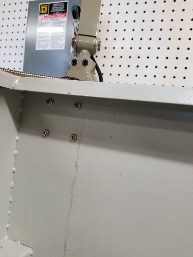
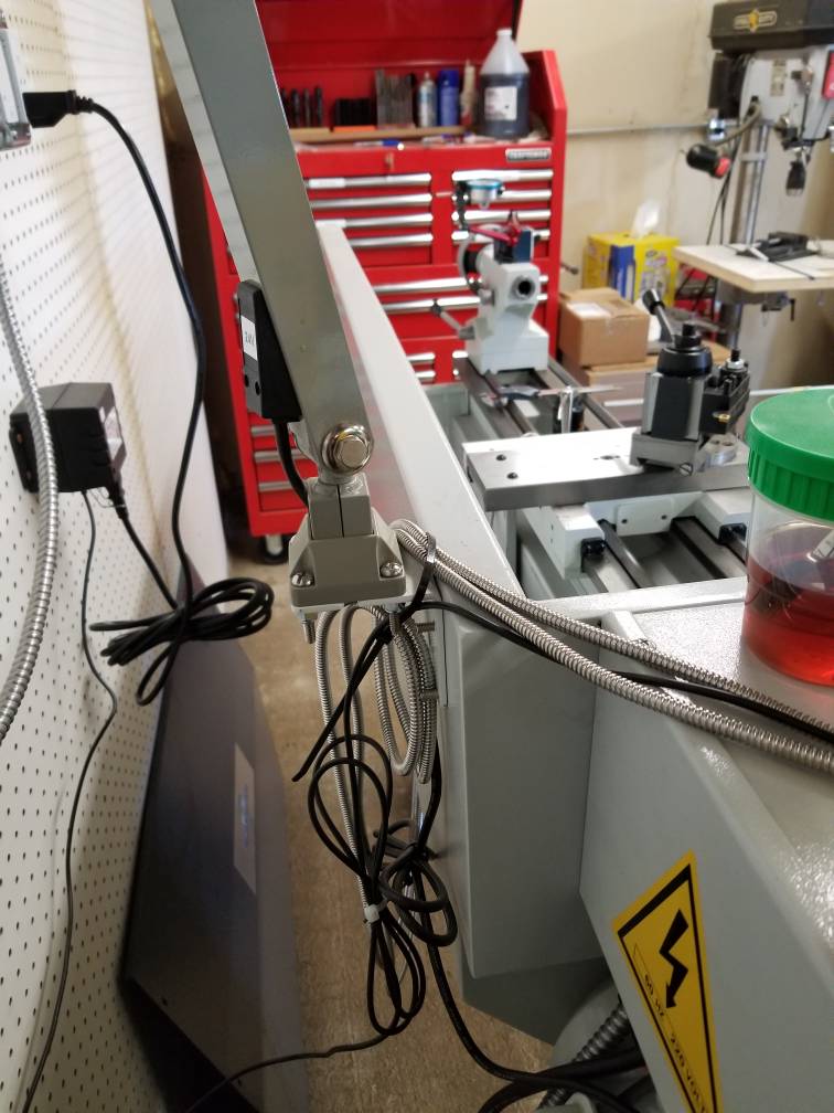
Next up is mounting the electronics, speaking of which... I couldn't find any mounting holes or documentation for the DRO or light. The 4 holes in the splash guard match the LED light bracket, but there were only 4 bolts & there are 4 holes on each side of the bracket matching 4 holes in the splash guard & 4 in the base of the light arm. Am I missing 4 bolts I need to scrounge up, or did others just do 2 on each side of the bracket? Also, where did you mount the DRO & Power supply for the DRO? I didn't see any obvous mounting holes. I'd kind of assumed there would be some as I got it with the DRO scales at least pre-mounted. Drilling a couple of holes isn't hard at all, but I should figure out if there are any pre-done holes somewhere I'm missing or where others have mounted their DROs & if they are happy with that spot. I peaked in the wiring box in back of the lathe, but didn't remember to check to see if there were convenient spots for a DRO & the light, or if I wire them into the wall.

After that it should just be wire the whole deal to the wall then level it all out. Then the fun of finally making chips.
 
The 4 holes in the splash guard match the LED light bracket, but there were only 4 bolts & there are 4 holes on each side of the bracket matching 4 holes in the splash guard & 4 in the base of the light arm. Am I missing 4 bolts I need to scrounge up, or did others just do 2 on each side of the bracket?

Sorry to resurrect an old thread but I have the same question. Mine was just delivered yesterday and I can't find any close up pictures of how to best mount the light.

Fallon, did you figure it out?
 
All 8 screws there match, so I either scrounged 8 matching ones or found the ones that came with the machine. It's been a bit so I forget which.
142d767fc8c67e6a4e94dd1ec9eb8c16.jpg
9736c1420d47fbbf73c9958f90ef59c2.jpg


Sent from my SM-N950U using Tapatalk
 
All 8 screws there match, so I either scrounged 8 matching ones or found the ones that came with the machine. It's been a bit so I forget which.

Sent from my SM-N950U using Tapatalk
I think you might be lacking some pegboard there behind the tool chest and drill press - just sayin' :grin:
One can never have too much pegboard & hooks/hangers...
 
Back
Top