[How-To] How (can?) a pilot light be added to a 3 phase drum switch?

keeena

H-M Supporter - Gold Member
H-M Supporter Gold Member
Joined
Jun 10, 2019
Messages
532
I have a lathe which has a 240v 3-phase, 2-speed pole-changing drum switch for selecting the motor speed. I'd like to add a pilot light to this switch when its in low or high to serve as a warning that the lathe is "hot".

The switch has 3 positions: off, low, and high. 9 total inputs: R/S/T, U/V/W-a, and U/V/W-b. The drum switch does not have any power to it until/unless the operator's spindle direction (on-off) lever is on. There aren't any additional terminal positions on the drum that I can take advantage of. The only thing could possibly use is continuity in any one of the legs. e.g. if R <-> Ua or R <-> Ub is connected.

Is there any way to get this to work without a lot of electrical gymnastics?

My only other option would be to modify the switch to add my own switch at the end of the drum switch's axle. There's very little room to do this - would take a bit of noodling to fabricate something.
 
Maybe something like this? Just put it on one of the three input phases to the switch.

Search on amazon:

"CR Magnetics CR2550-G Low Cost Remote Current Indicator with Green LED, 1.5 AAC Turn-On Point"​

 
Thanks @Reddinr! Current sensing won't work in my case; the drum switch won't have any current running thru it when its switched on because its downstream from the operator's spindle direction switch.
 
In its' simplist form, a full voltage pilot light across the output of the switch would serve. There are a couple of "assumptions" associated with that comment. The primary one being that power is available to the setup switch when the motor switch is out. Going phase to phase with a 240 volt pilot light would work. Your choice of which two phases to use.

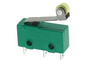
If there is no power in a static position, it's a" whole different ball of wax". Again, the simplist form would be a "micro-switch" mounted so it toggled when the switch was moved in any direction. Using the normally closed (NC & COM) contact to indicate when the switch was off the OFF position. The normally closed contact would then indicate a "setup" was in place. The simplist form would be an LED, resistor, and flashlight battery. Going up from there, I would highly recommend the terminals not be exposed with more than 12 volts or so supply. Wiring should be insulated at least 300 volts. TFFN is not, THWN is. A roller on the leaf of the uSwitch would make the contraption more resiliant.

Using "electrical gymnastics", (I like that term) there are many possibilities including low voltage indication. I concur with your desire to indicate a "setup" as live. Any machine that could move should be so indicated.

.
 
Last edited:
if you are just looking for power indication, a 220v lamp or LED cold be wired to 2 poles of the switch in parallel.
the lamp/led power would be controlled by the drum switch
 
@Bi11Hudson - there isn't any power in a static position. That is my challenge. When you say microswitch: I assume you mean to add a physical component right? That was my only other thought/option. Was hoping there was an electrically creative way to sense one of the legs connected w/in the drum switch without having to worry about whether or not there was current passing thru it.

And yeah - safety is exactly my concern. Currently there is only 1 master power light which illuminates when the main power switch is on. This isn't enough IMO. Its too easy to miss drum switch's position; its in an low position on the base and not very legible. I do have a habit to check it any time I'm going to measure a part while its chucked up, but an idiot light would help. :grin:

@Ulma Doctor - there isn't necessarily power running thru the drum switch so I wouldn't just be able to add a 220v bulb between 2 legs.

I am trying to replicate the "live" light you have when the e-stop on most lathes is not engaged. You can think of this drum switch a bit like an E-stop. But instead of being at the top of the component order it is at the tail end. Thus it usually will not have power until/unless everything before it is switched on, including the operator's 'final' control on the carriage apron.

It was probably done this way to minimize cost. I suppose it could have been installed further upstream at the expense of some additional components (probably an extra relay/contactor)
 
Last edited:
I'm thinking two tiny reflective opto sensors with a piece of foil on the drum switch rotor inside, and a simple transistor circuit to drive a pair of LEDs.
You probably want something a little simpler.
I can post a circuit if you are interested.
-Mark
 
So let me understand this better.
You have a main power switch, that feeds to this HI/LO drum switch, that feeds to the FWD/REV switch.
You want an indicator that will light when the HI/LO switch is in any position but off.
Do you want this indication regardless of the main power switch position AND regardless of the the FWD/REV switch position?
 
@markba633csi - I think trying to stuff anything inside the switch won't be possible, but adding optical sensors outside is possible. If I have make my own solution, I think the best bet is to add an encoder to the end of the drum switch's selector axle/rotor. The axle comes out the backside of the drum switch but there's very limited material to work with. I'd probably press on a larger wheel and go from there. Whatever the encoder switch mechanism is: I'll want to use it to power a 24v AC lamp (I'll be using the existing control circuit's voltage)

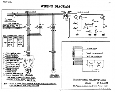
@Flyinfool - I've been simplifying the electrical description just for sake of discussion. A bit more accurately:

Main power 3 phase circuit
Main isolator switch -> 2 contactors (fwd, rev) -> overload -> drum switch -> 2 speed motor

Control circuit (I left out irrelevant items)
Spindle rev/off/on lever (the "go" lever on the carriage) -> control signal to fwd/rev contactors

I attached the factory wiring diagram; its a fairly simple setup.

I want an indicator light to be ON when:
a) main isolator switch is ON
b) drum switch is set to Speed 1 or Speed 2

State of any other switches do not matter.

EnterpriseL_WiringDiagram.png
 
I'm thinking two tiny reflective opto sensors with a piece of foil on the drum switch rotor inside, and a simple transistor circuit to drive a pair of LEDs.
You probably want something a little simpler.
I can post a circuit if you are interested.
-Mark
That method falls within the "electrical gymnastics" realm. A beautiful idea but having a low voltage circuit inside the high voltage cannister is a "no-no" unless there is absolutely no other option. There are a dozen or more circuits that would serve here.

A uSwitch can be had as cheap as 89 cents, possibly less. There are many options, the below is the source I use. Mounting would be a function of the shape/style of drum switch. The one I have on my lathe is a cheap (not to be confused with inexpensive) metal can. The uSwitch would mount on top, under the handle. or behind, rubbing on the setscrew. Another style being a through hole rotary switch where the uSwitch would mount on the back, rubbing against a flat face on the square operating shaft. Such that a corner (either one) would toggle the switch. Whether you use the nornally open or normally closed contact would be a function of how it was mounted and triggered.

Again depending on the physical design of the drum switch, a uSwitch could be mounted using small screws (M2 or Nr2-56), epoxy, or even CA (super-glue) cement. I wouldn't trust CA cement for long term holding on something this important. It could hold the uSwitch in place to prove the idea, then using epoxy or screws for a permanant fix. Some form of paper under the switch should be used, to protect the soldered contacts. I would use "fiche" paper because I have it for motor winding. Any form of insulator would do, especially if you use a low voltage circuit. Styrene as thin as 0.010" can be had at most any hobby shop and would do for even line voltage circuits.

.
 
Back
Top