How do we id an old South Bend lathe?

blu73

Registered
Registered
Joined
Mar 4, 2017
Messages
31
Greetings,
My brother just took delivery of an old South Bend lathe. All he has been able to find out so far from tags and stampings are this. A 13" swing over the bed ways, a 4 foot bed, what seems to be a manufacturing date of 9-11-1913, Catalog #34A, and what we think may be a serial number of 21053. I know that's not much to go on, but we need to start somewhere. As soon as I am able, I will get some pix to post here. We would like to get some information to start a search for manuals, charts and such to really understand the machine.

As far as condition, he says it seems fairly tight and he has found marks from what may be original scraping on the ways. He says the spindle nose is threaded and has an OD of 1-7/8". He didn't mention the pitch of the threads. No information on the spindle bore yet.

Well, that's it for now. Pretty vague, but again, it's just a start.

Thanks ahead of time for any help.
Russ
 
I would think if you took some pictures of the machine and post them that you would get the info you are after much faster!
 
Hopefully, I can get some pix posted this weekend. My brother and I are on different schedules thru the week, so.........

Anything we find out will be posted. Adding to the information base of these old machines makes the most sense.
 
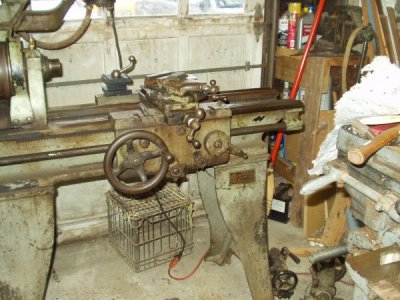
Okay, here are some pix of the old South Bend lathe. The first one is just a general view of the saddle and tailstock end.

288588

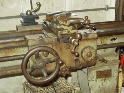
Next is a closer view of the saddle. Notice that there is no index dial for threading. The machine seems to have the proper hardware in place to thread, along with a chart attached to the guard that covers the gears. Our obvious question is, how does one successfully thread without the index dial? Is it possible to add an index dial to the apron? Another question. What are the two T-slots cut into the top of the saddle used for?

288589

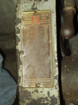
Next is one of the tag attached to the guard. It is possible to make out the date just beneath the red "S" at the top of the tag. It reads 9-11-13.

288590

None of the pictures of the tag showing the swing, bed length, and catalog number came out very well, so I'll just repeat here that the tag states a swing of 13 inches, a bed length of 4 feet and a catalog number of 34A. I was jammed into a corner trying to get a shot and it didn't work out too well. Here's the best one, but it's pretty useless. The 4 foot bed dimension is the total length of the bed from one end of the lathe to the other.

288591

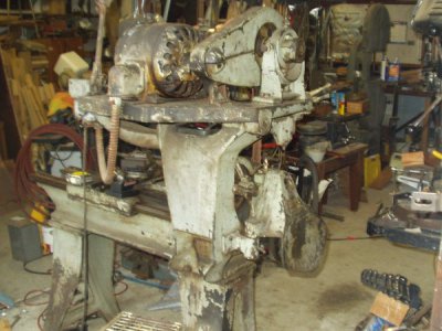
Here is one showing the motor and mounting hardware. It's hard to make out, but there is a lever at the right side of the mounting plate that causes the entire upper portion of the assembly to rotate about the shaft that can be seen at the near side of the plate. This rotation causes the flat belt to tighten between the upper and lower pulley shafts.

288594

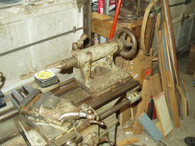
Next is the tailstock sitting in place. We tried to eject the dead center by retracting the ram but had no success. Is that how it's supposed to be done? It doesn't make much sense to have to remove the ram every time a tooling change is needed in the tailstock.

288595

Here is one showing the tag on the motor. Again, not a very good shot, but we are more interested in the knob at the bottom of the image. It moves about an inch to the left within a slot and we have no idea of its purpose. Anyone out there with knowledge of that?

288596

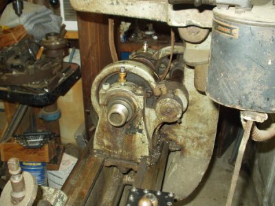
Here is a look at the spindle nose. It is threaded 1-7/8" - 8. The hole in the spindle seems to have a constant taper from this end of about 1-1/4" down to about 1" at the far end. Facts about that taper would be most welcome.

288597

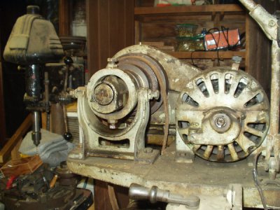
This is an interesting shot. Notice the castings on the end of the motor and the shaft of the pulley assembly. They seem to be reservoirs for oil. The one on the motor even has a drain plug. Also showing on the top of the casting on the motor is a hinged cap. Lifting it reveals an oil slinger inside there. The four bolts in the casting around of the pulley shaft are for alignment. There is a second similar casting at the other end of the shaft. With the adjustments available, the pulley shaft can be fine tuned for alignment with the spindle. Amazing.

288598

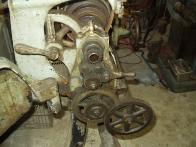
Finally, at least for now, is a picture of the drive gear arrangement. The lever at the left engages spur gears on the spindle. The lever at the right seems to be a way to reverse the feed direction of the lead screw. Again, more information would be most welcome. The more details, the better.

288599

Well, that's about it for now. I'm sure there will be more to come.

Russ
 
Last edited:
I believe the 9-11-13, is just indicating that the tag applies to the 9", 11", and 13" lathes. I can't see them making up new plates everyday. And its to nice looking to have been made on 9-11-2013. :chunky:

The T slots, just add extra versatility to the lathe. There is a few Youtube videos, with the operator bolting a casting down to the carrage, and using a long bar from the chuck, to the tail stock, with a cutting bit attached, and line boring the casting, by moving the carriage. Also make a convenient place to hold the 4 way tool post.

Is there a threaded hole where the threading dial normally mounts? You can thread without it, just need to keep the half nuts attached, and reverse the lathe to setup for the next pass.

Thanks for the pics, it is a beauty under the grease. I love the style of those old motors.
 
Benmychee and Herk, thanks for the links. Tracking down info is a bit of fun a lot of times.

Superburban, thanks for the thought on the 9-11-13 business. That makes a lot of sense, as the serial number and the other tag with the swing and length puts the build date sometime in 1919. A different perspective is valuable. I tend to get stuck along a certain line of reasoning, and your statement reminded me to think in other directions. As for a tapped hole to mount the threading dial, nothing there. Do you know if it's possible to retrofit a dial?

As for my comment on the tailstock ejecting a tool, it turns out the dead center that was in the ram was a bit short. My brother got it apart and installed a different tool and was able to eject it as we thought it should.
 
Here's a couple of tidbits:

A #4 Morse taper measures 1.231 on the wide end down to 1.020 on the narrow end so that might be what you have.

The motor has a cup for oil likely with an oil slinger ring that dips into the oil to lubricate the shaft. I have several of those motors and
they hardly need attention other than to top off the oil periodically in the cup, a good system for motors with bushings.

On the ends of the lathe drive I see what looks to be the remains of drip oilers. From the photos, the headstock and tailstock bearings(bushings)
look to be made of brass or possibly babbitt.
 
Last edited:
Not much new to add at the moment. Still cleaning things up. Adapted an indexable tool post to the compound.

A SCARY MOMENT. My brother was cleaning the stepped pulley drums on the spindle and had the belt cocked to one side so there was no tension at all. He did that to rotate the spindle by hand while cleaning it. He had the work light on the lathe plugged in and was using that to see better. For whatever reason, he decided to check out the drum switch. When he moved the switch handle, THE MOTOR STARTED. He was resting his hand on one of the spindle drums. Luckily for him, he had the belt in a completely slack condition. It turns out the lathe was wired up to run through the lamp cord only. We both thought the cord was only for the work light, because of the size of the wire. Something like 18 gauge.

Just goes to show you how an assumption about something can lead to an injury in a heartbeat.
 
Back
Top