How to layout holes on an 8" diameter plate

bigblock61

Registered
Registered
Joined
Jul 17, 2019
Messages
13
I have a 4" rotary table for my Grizzly mill. I'd like to make an 8" top plate for it so I can have room to bolt down a 4" piece. My thought is to make the top plate with as many holes as I can drill in it and still have the plate remain strong. I'm thinking 3/8" threaded holes 3/4" on centers. I would need the center hole to match up with the center hole on my rotary table and 4 holes roughly 3" around the center hole to bolt the top plate to the rotary table. What is the best way to lay out a pattern of holes 3/8" by 3/4" on centers?

My first thought is to figure out each diameter from 7.5" to 3" staying as close to the 3/4" centers as possible. 7.5" C=(2 x Pi x r) a circumference of 47.1". A spacing of .785" = 60 holes. 360 \ 60 = 6 so a 3/8 hole every 6 degrees slightly larger than 3/4". Do that for the next smaller diameter and so on. My question is, is my thinking right and is there a better way of doing it?
 
I would probably just lay out a pattern on the plate with 1" spacing in both directions, with a square grid pattern. The plate for my own RT is blank and only gets holes added to it as needed, the lazy man's approach. It does put the holes right where you want them for the job at hand, and it also adds time to the projects, but not to making the plate...
 
I would probably just lay out a pattern on the plate with 1" spacing in both directions, with a square grid pattern. The plate for my own RT is blank and only gets holes added to it as needed, the lazy man's approach. It does put the holes right where you want them for the job at hand, and it also adds time to the projects, but not to making the plate...

Interesting idea but since the plate I have is already an 8" circle, putting a square pattern would limit my choices for clamping options.
 
Big Block,
One of my, to do, projects is adding a plate to the rotary table to be a clamping, sacrificial plate.
I would like to add a fence that is parallel to the milling machine table X feed when the rotary table is set to zero.
In order to accurately accomplish this the plate needs to be installed to the RT quickly and easily.
A smart fellow in our local group has his plate set up with close tolerance pins that slip into the RT's t slots.
Just throwing ideas around.
 
Last edited:
Look at the first four videos in this list:
 
I would also not make the plate round if it is currently square. The idea being that we do not know what our next project might be, so why cut anything off or drill anything until it needs to be for the current job. I would just build a good centering arrangement (spud, Morse taper, or whatever) and something like a tight fitting pin (or more) to set the clock position of the plate. Done right, it could also act as a fixture plate for your mill vise. Or for the mill table. Or for a lathe chuck. The more things you do to the plate up front, the more limited become the future possibilities for using the plate...
 
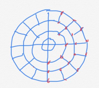
You could lay it out like a spider web wth diameters increasing every 1-1/2” and rays radiating from the centre. When the spacing of holes becomes too loose or too tight for your liking, add or delete a set of rays. Personally I think 3/8” holes on an 8” plate are way too big. I would go 5/16”, no more. It’s for clamping on a 4” RT, not holding up an engine block.

I do tend to agree with Bob though, regardless of where you put your holes there is an equal chance they will be in the wrong place. Been there several times.

-frank

D104AC96-57A4-458A-BBD4-6761553DFF8F.jpeg
 
Some time back I wrote up a little spreadsheet for calculating bolt circles. It's attached. DROs would be a handy thing to have for this kind of business, but not absolutely necessary.
 

Attachments

  • bolt circle calculator.xls
    10.5 KB · Views: 15
On a fixture plate for a 4" RT, I would not make the threaded holes larger than 1/4"
 
Back
Top