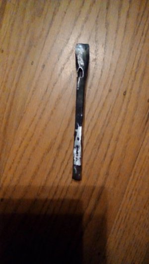
I am trying to make a straight forged Armstrong tool holder for my South Bend lathe, and I was wondering how to make the square hole for the tool bit. The left and right hand tool holders look straightforward since they are bent, but the straight one is not because it is bent. A hole at a fairly shallow angle has to be drilled in the nose. Then, this hole has to be broached square. This is too challenging for me to do hot. Deep holes more than three times the punch diameter are tricky. I know exactly what is going to happen if I try to drill and file it. I am going to spend a lot of time forging the shank and upsetting and shaping the nose. Then, I'll drill an off angle hole which I'll have to spend several hours looking at as I file this long narrow hole to square with a thin delicate square file. About 2000 trial fits will be necessary to get a sliding fit over the length of the hole. All the while, I'll be looking at the slanted hole, and wishing that it was straighter, knowing full well that if I remade the tool holder, it would turn out the same.
This is really discouraging. There is even more that is discouraging. First, I looked at eBay, and there was a 0-S tool holder with a crooked drilled hole. Even the factory made one could not escape the aforementioned fate. Note that some slanting of the hole does not affect function, because with the short projection from the nose of the tool bit, the functionality is unaffected. Second, I did exactly what I said above, and cannot bear to expend several evenings of effort filing on this obviously crooked hole.
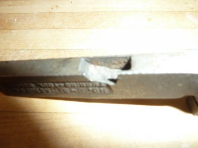
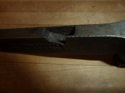
The hole was drilled on a good drill press with a stub length drill. The hole was started with a tiny divot from a center drill, followed by a spotting drill. The tool was clamped to an angle plate, which was clamped to the drill press table. I cannot seem to get the drill exit hole to line up on the long holes.
One curious observation is that in the eBay photo, the exit hole is circular, while on mine, it is oval due to the exit angle. So, the manufacturing process is clearly different, but I cannot figure out how or was done. The lantern post was easy. Just forge and offset the head of a railroad spike and slot punch the shank. The dished ring was also easy with a rounding hammer. I know a quick way to fix this. Slice out the side of the hole with a hacksaw, clean up with a (beefy) file, then tig weld the offcut back in.
Any clues to do it correctly? Is it possible to avoid broaching or even worse, filing? It's obvious that the exit hole is no bigger than 1/4" in the eBay photo, since that would weaken the shank. That would make broaching even more challenging. But, it almost certainly wasn't tig welded, either.
This is really discouraging. There is even more that is discouraging. First, I looked at eBay, and there was a 0-S tool holder with a crooked drilled hole. Even the factory made one could not escape the aforementioned fate. Note that some slanting of the hole does not affect function, because with the short projection from the nose of the tool bit, the functionality is unaffected. Second, I did exactly what I said above, and cannot bear to expend several evenings of effort filing on this obviously crooked hole.
The hole was drilled on a good drill press with a stub length drill. The hole was started with a tiny divot from a center drill, followed by a spotting drill. The tool was clamped to an angle plate, which was clamped to the drill press table. I cannot seem to get the drill exit hole to line up on the long holes.
One curious observation is that in the eBay photo, the exit hole is circular, while on mine, it is oval due to the exit angle. So, the manufacturing process is clearly different, but I cannot figure out how or was done. The lantern post was easy. Just forge and offset the head of a railroad spike and slot punch the shank. The dished ring was also easy with a rounding hammer. I know a quick way to fix this. Slice out the side of the hole with a hacksaw, clean up with a (beefy) file, then tig weld the offcut back in.
Any clues to do it correctly? Is it possible to avoid broaching or even worse, filing? It's obvious that the exit hole is no bigger than 1/4" in the eBay photo, since that would weaken the shank. That would make broaching even more challenging. But, it almost certainly wasn't tig welded, either.