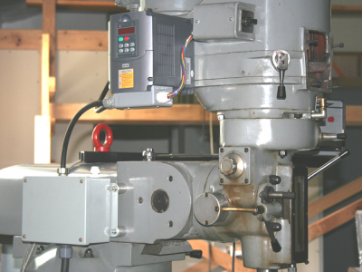
Huanyang Vfd On A Bridgeport Clone

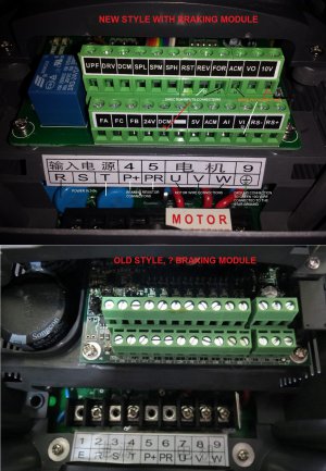
The build was for another forum member (but it looked just like yours in the connections, see picture), I mostly use the Hitachi VFD units. Not a big fan of Huanyang VFDs because of reported reliability/programming issues, the power terminals are undersized for their load rating.... There is no harm in attaching the braking resistor since you have it and see if you can dial down the braking time. You would get an over voltage error if you push the time down too low. A mill is not as critical as a lathe, so you can live with a 5-6 second stop time. There is no real point in using extreme braking times in normal use, as it does put more stress on the motor and drive train. You can program an E-Stop (or safety brake switch) in some units to change the braking time, i.e. run 2 stage normally and switch to 1 stage for emergency braking.

VFD wiring.jpg
 
There are extensive posts available online with schematics and modifications to provide the circuitry when missing. It is compelling information. My PC Board matches what is being reported.:confused:

mksj, after your earlier post, I attached the resistor I have... and lo-and-behold... NO DIFFERENCE! :mad: Unless there is something I'm missing in the setup, all indications are that there is no Braking Resistor support.

I have a suspition that the VFD in the image above is the same. :eek:
 
Might be various models, definitely was working on the one I installed (2 second stop on a lathe), but I have also read the treads the Huanyang VFD may be missing the external braking components. There are other brands of VFDs that this is also the case, like some versions of the Teco's, KB electronics, etc. I would contact the vendor that sold it to you and see what they say, or if it can be returned. Sorry, but the Huanyang VFDs leave a real bad taste in my mouth, and I question their long term reliability, but others report they are fine, so YMMV.

Anyway, attached is the PDF parameter file and changes that I used for a 2HP motor. I would check PD029-PD033 values.
 

Attachments

  • Huanyang VFD program variables for 2 HP motor.pdf
    58.2 KB · Views: 74
Thanks Mark,

The parameter file will be very useful. :) I could contact the vendor, but since I got it on eBay, they probably won't have much useful information. I'll give it a try though.... :confused:

I understand the "bad taste", I concur. I have other brand VFDs and I got them before I knew much about them. Some have the capability of braking resistors, others don't. Fortunately, I don't need to have anything different than what I have working now.

The only reason for having an aggressive decel is for power tapping. It is done at relatively low RPM, so even without a resistor it is satisfactory. But I actually prefer coasting to a stop and using the manually operated mechanical brake in the head. It's how I've been using a Bridgeport for over 30 years....;)

I have a Bridgeport BOSS3 CNC that I plan to put one of my VFDs on. That one also won't support a braking resistor (but at least they don't lead yo to believe otherwise), but I can set it up to coast to stop and I can actuate a brake with the CNC control (if necessary).
 
After getting the VFD working essentially the way I want, I noticed that at certain RPMs there is vibration that I don't like.

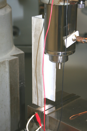
So I got an idea.... :rolleyes: If only I could find a way to know the relation of out-of-balance to the rotational position - you know, like a timing light, I could then drill holes in the heavy side and bring the spindle closer to balance. What I came up with is, if I could use the motion of the vibration to close a switch (or something similar), that would light an LED and shine it on the brake drum below the micro-v pulley I made. I can put marks on the casting to help locate the position of the out-of-balance. To get more motion from the vibration, I extended the quill and clamped a section of aluminum channel to it to extend the "lever arm" as far as possible, like this:
balance.png

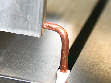
I put a piece of solid wire in the vice as a contact point:
contact.png

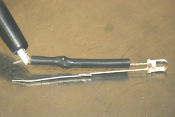
I used clip leads to connect a 9 volt battery to the contact wire and a superbright LED (a current limiting resistor is already installed under the heat shrink):
LED.png

I then cut pieces of masking tape to make indexing marks around the perimeter of the brake drum. Then I turned on the spindle and adjusted the RPM to find a resonate frequency of the milling head so it would shake as much as possible, and played with the contact gap while shining the LED on the marks:
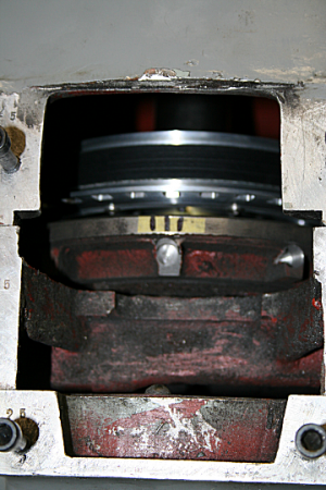
drill.png

I then drilled holes in the thick part of the casting to lighten the heavy side of the drum. I experimented with turning the spindle forward and reverse, and then split the difference between the readings (apparently there is some kind of phase shift with the setup). The amount of wobble at the contact point is only a few tenths on a thousandth of an inch. I fount that I could push at the top of the head to delicately influence the gap and adjust the duty cycle of the LED. There is a balance of the brightness of the LED vs. the accuracy of the indication, depending upon how much of a rotation the LED is lit.

After a couple of hours of messing around, I balanced the spindle the best I could within the limitations of the setup. And it made a BIG difference. The spindle is SOOOO much smoother!:applause 2:
 
Last edited:
I think that is one of the most interesting balance setups I have ever seen. Good thinking! :encourage:
 
Thanks Jim,

It leaves a lot to be desired, but it did the job....:)
 
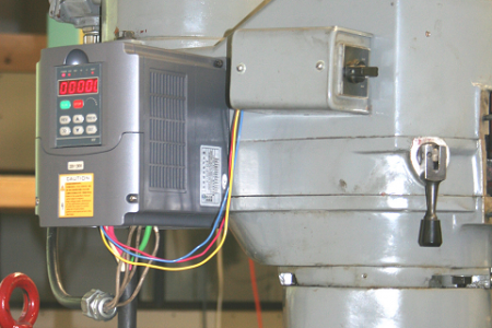
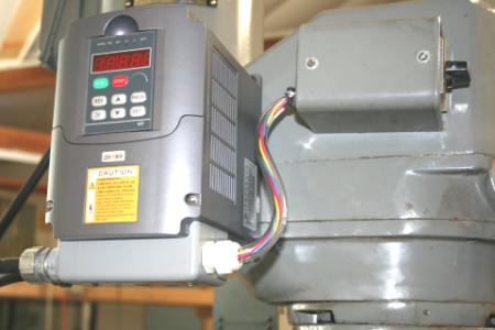
So I am now "cleaning up" the wiring. I don't like the way the high voltage wires are just hanging, so I looked for a way to cover them up.

Before:
b4.png

After:
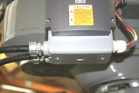
conduit.png

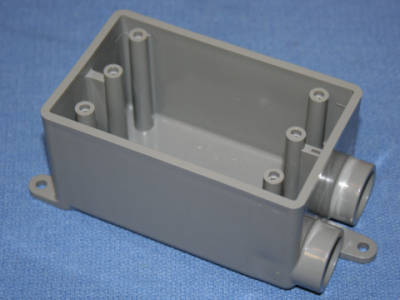
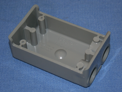
I started with this...
Image1.png

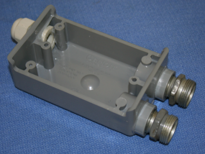
And modified it...
Image2.png
Image3.png

I drilled two holes in the case and epoxied nuts inside. Here you can see them holding the cover.
conduit+.png
 
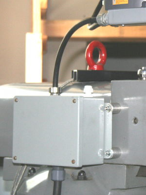
This morning I added a junction box with a power switch (so I don't have to keep plugging and unplugging) to the wiring. The box will also include the 5 volts required for the tachometer that I'll be adding (it has the strain relief on the top of the box but no wire yet).
Image2.png

The power switch is on the back of the box to keep it away from swarf. I mounted the box on standoffs so that swarf would be less likely to pile up between it and the machine. It turned out to be good for the clearance of the power chord out the bottom. The box was something I had lying around, and it had some holes in it already, and the hole in the bottom was one.

Here is a wider view, you can see the hole in the front of the head where the mechanical speed change crank used to be. I'll be putting a cover on it with the tachometer:
Image1.png
 
Back
Top