Huge Steady Rest

springer

Active User
Registered
Joined
Dec 29, 2013
Messages
284
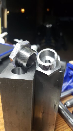
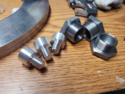
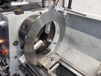
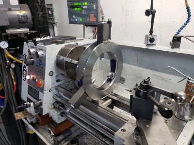
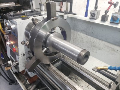
So have have a PM1340GT and the steady rest that came with it. As it was, I could only fit about 2-1/2" through it. I modified the top nuts and got about another 1/2" capacity which got the first part i needed to fit. On to the next part and now i needed to hold 5" stock.

I'm building a vise because my 12 year old HF special is finally annoying enough to warrant a new project.

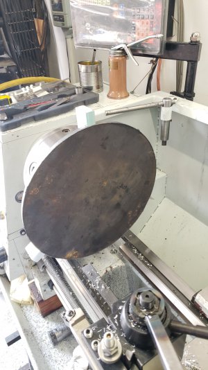
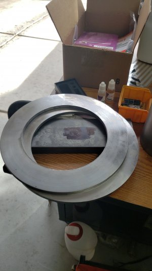
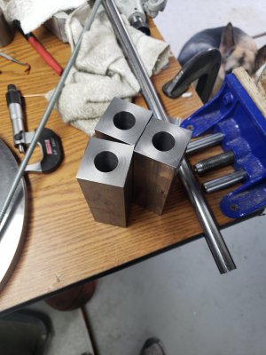
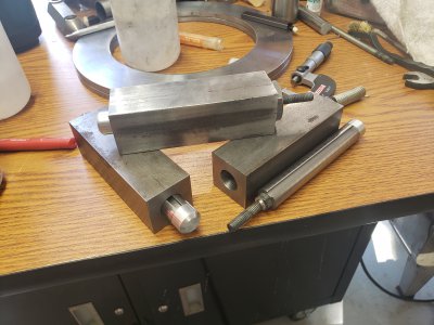
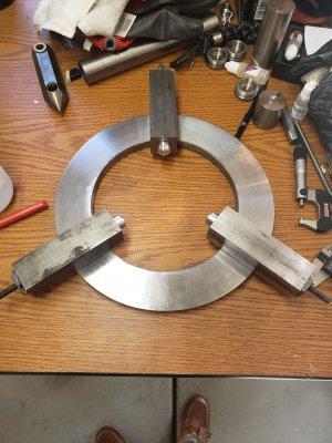
Anyways, I bought 2 3/8" round plates, some 1-1/2 square stock and some 3/4" keyed shaft. The rest was just stuff from around the scrap bin.

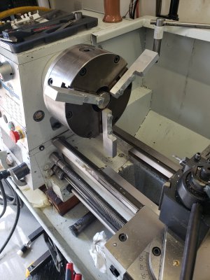
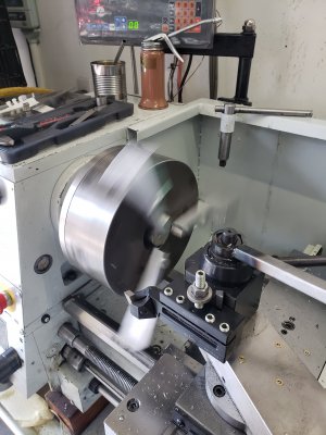
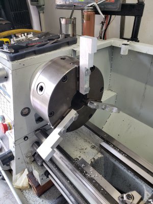
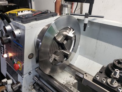
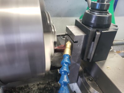
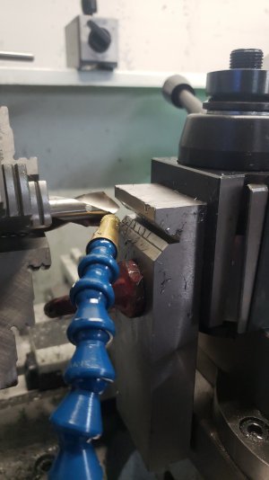
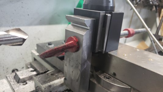
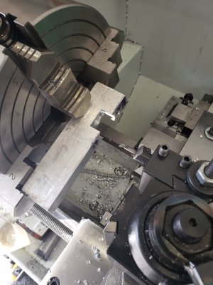
To machine the large plates, I had to make some janky soft jaws for the 3 jaw.
20200118_103950.jpg20200118_120141.jpg20200118_121904.jpg20200118_124333.jpg20200118_130115.jpg20200118_205018.jpg20200119_132718.jpg
 
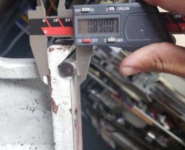
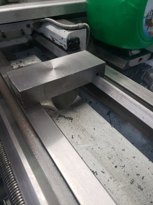
Next was the base plate that rides the ways. I dont have my mill anymore so I had to improvise. Worked out pretty well. I measured the thickness of the "v" using a rod, then matched it on the new piece. Worked great, very nice fit, I kinda surprised myself.

20200119_160500.jpg20200119_170024.jpg20200119_165523.jpg20200119_171814.jpg20200119_174401.jpg
 
That is some creative problem solving. Nice work.
I have to say the pics of those soft jaws whirling through the atmosphere are a bit terrifying!
 
Someone got some serious shop time in - that's for sure. :encourage:
 
Springer,
Very impressive work. :clapping:
I'm wondering how many hours you have in that project? Do tell.
 
Springer,
Very impressive work. :clapping:
I'm wondering how many hours you have in that project? Do tell.

I guess I didnt really keep track, but thinking back I'd estimate about 20-25 hours. I kinda worked on it in between other parts of my vise as I got bored or certain materials showed up from ebay. The hardest part was figuring dimensions and matching parts to other parts that weren't built yet. If I had to make another, itd take half as long.

That is some creative problem solving. Nice work.
I have to say the pics of those soft jaws whirling through the atmosphere are a bit terrifying!

Honestly, it was absolutely terrifying. I had less than 1/4" between the ends of the jaws and the ways on the lathe. I had to hang tools out as far as I could so the carriage wouldnt hit.

Spinning the 12" discs was just the same. I treepanned one of the holes and it was super sketch because those jaws were no where close to being rigid. I ended up plasma cutting the other and it saved a bunch of time. This is what got me looking for a larger 4 jaw but I made due and doubt I'd often use such a large chuck.
 
And just in case anyone is wondering, 7075 aluminum is wearing great (hardly at all) for the tips of the steady, but it is an awful choice for a bearing material. I'm sure everyone knew that except me buts it's what I had on hand so I tried it. I really drags on the work and bogs my lathe down something fierce with just the slightest amount of too much pressure.

I'm going to melt and cast some brass rods later today and make some new tips to see how that goes.
 
I made a steady rest for a 24" Nebel lathe many years ago to nearly the capacity of the lathe, made a profile drawing of it on template paper and had it burnt out of 1 1/2" steel plate by the local steel supplier who had an electric eye burning machine (days before CNC) I machined the hinge joint 1/2 & 1/2, like commercial ones are done, slotted the other side for a hinge bolt and milled slots for the shoes and welded tapped plates for the shoe adjustment screws and welded a bottom block on for the way clamp, I think I used cam rolls for the rolling surface on the shoes, If I had done it years later, I would have likely mad a wood pattern and had iron castings made, as I more recently did for my 9" Monarch lathe.
 
Back
Top