I am installing a nifty Chinese DRO and set of glass scales on my grizzly 12x36. I am done , except the z axis chip shield. I am pausing here to check the accuracy of the set up, as I am running out of time to complain if there is a problem. I don't need a chip shield to test these, so it can wait. Currently I have a one inch standard used to calibrate micrometers and such. I have no Jo blocks. I have an er40 collet chuck mounted to the spindle with a nice ground flat face on it. It's the kind that came as a plate with an er40 chuck protruding from it, around the chuck is the ground flat. I have .0001 Interapid test indicator on a mag based noga arm. I have an Aloris knockoff qctp on the compound or I could also attach a vertical milling slide in place of the compound. I'm hoping to use this gear (preferably without making parts) to check the cross slide and carriage scales against the 1" standard. Something like hold the standard in a repeatable fashion against the chuck face and bring the indicator in till preloaded and zero it as well as the dro. Then remove the standard, bring the indicator in until it again reads zero and check the readout. I'm hoping to pick other peoples brains for solutions to holding the standard, indicator and general set up. Thanks for making my puzzle your puzzle.
-
Welcome back Guest! Did you know you can mentor other members here at H-M? If not, please check out our Relaunch of Hobby Machinist Mentoring Program!
You are using an out of date browser. It may not display this or other websites correctly.
You should upgrade or use an alternative browser.
You should upgrade or use an alternative browser.
Ideas for proving DRO calibration
- Thread starter LEEQ
- Start date
- Joined
- Feb 1, 2015
- Messages
- 9,602
What do you have in the way of a micrometer or calipers?
- Joined
- Feb 1, 2015
- Messages
- 9,602
I ask this because from your description, the only article of reasonable accuracy is your 1" calibration standard which is not the best for determining the calibration of a DRO scale. (too short) I would prefer something like 4 - 6". The longer the better.
For the z axis on my lathe, I used the 3" length of a 1-2-3- block. I had measured the actual length with a micrometer. I clamped a block to the ways of my lathe and I ran the carriage to the block and zeroed the DRO. Then I moved the carriage and inserted the 1-2-3 block between the carriage and the clamped block, ran the carriage up to the 1-2-3 block and compared my DRO reading to the 1-2-3 block dimension.
For the z axis on my lathe, I used the 3" length of a 1-2-3- block. I had measured the actual length with a micrometer. I clamped a block to the ways of my lathe and I ran the carriage to the block and zeroed the DRO. Then I moved the carriage and inserted the 1-2-3 block between the carriage and the clamped block, ran the carriage up to the 1-2-3 block and compared my DRO reading to the 1-2-3 block dimension.
- Joined
- Jun 12, 2014
- Messages
- 4,808
You can just start out by comparing their overall accuracy to the dials on the lathe. Take out any play in the dial, zero it and the DRO and then compare to the DRO over each turn, and over something like 10 turns. This will tell you incremental and overall travel information in relation to the dials. If they compare then good enough.
- Joined
- Nov 9, 2015
- Messages
- 406
Maybe it's just my lathe, but I had a hard time using dials as a check for DRO accuracy. It appeared to me that wear in the screws led to differing dial accuracy along the length of the screw. I ended up using a 4" gage block as RJ describes to measure accuracy of the DRO.You can just start out by comparing their overall accuracy to the dials on the lathe. Take out any play in the dial, zero it and the DRO and then compare to the DRO over each turn, and over something like 10 turns. This will tell you incremental and overall travel information in relation to the dials. If they compare then good enough.
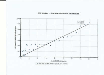
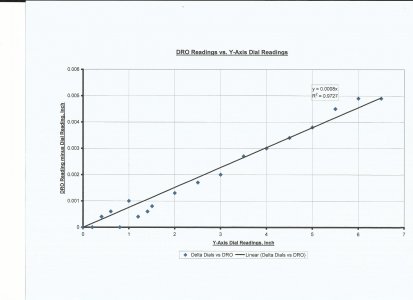
As a FYI, I have attached plots of dial readings vs. DRO output for two of the three axes on my Smithy 3-in-1. You can see that wear on the X-Axis lead screw at the headstock end led to higher inaccuracy relative to the tailstock end.
Since the DRO looked very accurate by the gage block method, I conclude that over the entire length of travel, there is an average of 0.0004"/inch of inaccuracy in the lead screw dial and 0.0008"/inch in the crossfeed screw dial. But again, it varies along the length of travel.


Last edited:
- Joined
- Feb 1, 2015
- Messages
- 9,602
My Grizzly G0602 lathe has pseudo inch dials. i.e., .4000" by the dial is actually .3937". As long as you realize this, the dials could be used as an indicator. If I were using the dials, I would make my calibration points at either end of the lead screw travel to avoid the region of highest use and most wear. One must realize that there will be uncertainties in manufacturing of the lead screw which could affect a DRO calibration though..
I would prefer to use a block, "calibrated" with a caliper as a "standard" over the lead screw dial. A 5" block can be measured to within a thou or two which would provide a DRO calibration to within 40 ppm. This is essentially five digits in the DRO calibration factor.
An understated fact is that DRO's are not necessarily calibrated out of the box. @Bob Korves brought this to light in another thread. https://www.hobby-machinist.com/threads/dro-error.64376/#post-534589 post#8
I was unaware of this myself and had used my mill DRO "as received" for for fourteen years. The calibration procedure is not particularly well documented, especially in the Chinese manuals. In my case, the error wasn't great to cause problems with most machining but would lead to machining errors over longer intervals.

