IGaging DRO EMI Problem

I am using a digital oscilloscope with a 10-1 probe set to 1. Ground of the probe is not used. Probe tip touched to spindle, mill table, scale body, vertical column to make noise measurements. 60 Hz is detectable and the pulse rides on the 60Hz.

This was done a lab environment using safety precautions.

Safety First and if you don't know, educate yourself please.
 
Got to have pictures. Took two this morning. This is the DRO and the scale that shows the 4-40 threaded hole and Kapton tape. Vinyl electrical tape will work too if you keep oil off it so the adhesive doesn't fail and get gooey.

IMG_7711.JPG

Next is the ground strap I started with, cut in two, and used a 2.2uF. When the scale is mounted, the free end shown below will be secured to the scale with a 4-40 by 1/4" hex drive screw with lock washer.
 

Attachments

  • IMG_7712.JPG
    IMG_7712.JPG
    1.3 MB · Views: 9
I got everything mounted and wired.

Still have failure in DRO as they wander.

Back to troubleshooting!
 
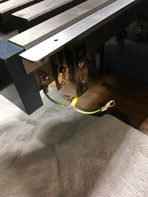
I found that hardwiring the scale to the DRO's internal ground, along with soldering 1uF caps across the sensor's Vcc and Ground, worked for me. The sliding contact to the scale doesn't seem to work very well, at least not for aluminum scales. Just the caps have worked for some, it seems to depend on each individual machine the DROs are installed on.

From what I've observed, noise can affect the DRO in two different ways. One is where it gets into the clock and data lines, causing temporary glitches in the display that stabilize after the noise source is turned off. The other way is that it apparently causes the power supply voltage the sensor "sees" to bounce around a lot. When this happens, the displayed position changes and doesn't recover when the noise goes away. My problem seemed to be mostly (but not exclusively) due to the latter issue, hence the added caps between Vcc and Gnd.

Some have suggested putting RC filters on the clock and data lines to filter out the noise, but I think that would be problematic. The display unit generates the clock and the sensor unit generates the data, which is synchronized to the clock signal. If the clock line is filtered, the sensor "sees" a delayed clock, thus delaying its data output; and filtering the data line results in a further-delayed data signal going back to the display. The receiver could miss the data transitions. You could write some code for an Arduino or the like that takes the delays into account, but if I had to go that far I'd think hard about going to a real DRO combo -- magnetic/optical scales + display.
 
My iGaging setup is somewhat different in that it is an earlier version. I also use the TouchDRO and an Android tablet for my readout. I had problems with sudden jumps to som e multiple of .2 when my lathe motor was switched off. Adding capacitors across the supply lines in the pickup heads removed almost all of the problem. I added a solid state relay to replace the mechanical switch for the motor which eliminated switch bounce and this solved the problem.

Another issue that I see is that the readout would momentarily stop updating on occasion. When it resumed, no counts had been lost. This indicated to me that the actual counting took place in the pickup and the updated ascii data was being sent to the readout. I suspect that it occurs because of the Android tablet rather than than the iGaging scales or the TouchDRO adapter. While it is annoying, it hasn't been a deal stopper.
 
Yes, when the stop switch is used, some multiple of 0.2 occurs. I imagine there was a person or two that designed the original dro that worked great. Then the new kids showed up with their cut and paste designs and zero knowledge of noise coupling. Increase the price on the new model and it doesn't work so just cut follow up and support. One comment that I just loved was "they use whatever cable falls off the truck that day". Well eventually the bugs will be fixed and we will have stable dro at a great price!
 
The ability to reject electromagnetic interference is EMC or electromagnetic compatibility. The measure of generated electromagnetic interference is EMI. A good part of the problem for me at least, arose with the EMI part. The filter capacitors in the pickups greatly reduced interference but the final solution was to replace the noisy power switch in the lathe with a solid state relay.

Frankly, with an electronic lead screw and DRO on the lathe, I am surprised that there isn't more interference. I am currently working on replacing my OEM notor with a PWM controlled brush type DC motor which is literally switching on and off a 10,00 times a second and with the experimental setup, wires a strewn all over and yet, I have had no problems with either the DRO or the ELS..
 
The final solution for the setup on the Mill was to replace the non shielded cables with shielded cables cut to length needed for each axis. Bypass capacitors remain on the insulated scales from ground. Cured the Y, Z axis, but X axis required 2 ferrite cores using one at scale and on at the head. The next step would have been to use bypass cap on VCC but was not required on this set up.

In the future, iGaging will be off the list for DRO. I love most of the stuff from China as the quality is usually miles ahead of the junk made in US, and the prices are affordable.

At this point the setup works awesome and I am only out some free time.
 
Back
Top