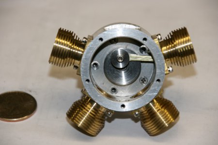
I'm making a Halo !!

Halo Valve Plungers

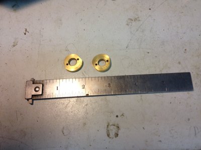
Plunger1.JPG

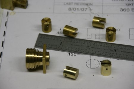
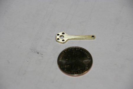
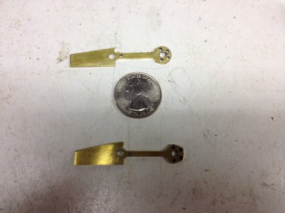
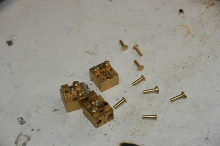
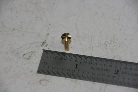
The Halo uses a pair of 3/16" diameter balls as the valves for intake and exhaust. The balls seat down in a counterbored hole in the head. Air pressure (and I guess a small spring) hold them seated and prevent the air pressure (or steam) from entering or exiting the cylinder. The Valve Plungers, one shown above, displace ball from its seat allowing air to pass. The rocker arms press the plungers down when the push rods and the cam followers move them..
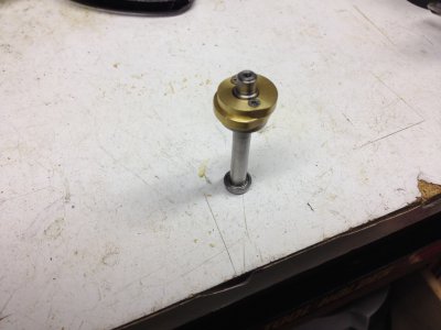
Plunger2.JPG

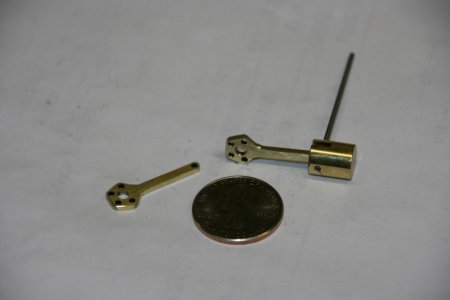
The plungers start out as 1/4" (.250") brass rod. I carefully turned the .125" shaft of them to be a slip fit in the .126" reamed holes in the head for them. Too tight or rough and there will be too much friction for them to move freely. Too loose and the compressed air will leak out around them and degrade performance. The head of the plunger is rounded to reduce friction with the rocker arms.


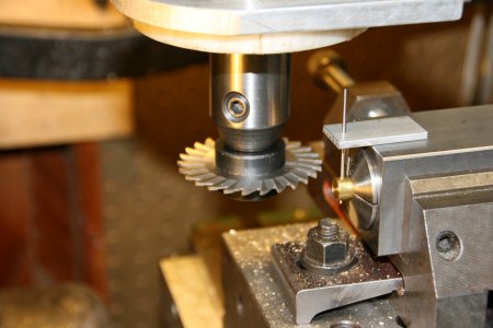
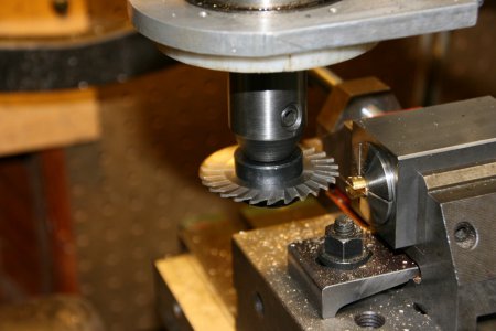
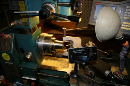
Above is a short video of how I rounded the head of the Valve Plungers. I like watching it. It does seem like I should have moved the ball turner further away before sticking my fingers in there! I used a 1/8" 5C collet with a stop in the back to hold all the plungers in the same place. I experimented with my ball turner to get a nice looking radius.
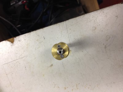
Plunger3.JPG

The above is "the making of the movie" photo!

Cheers
Dave
Plunger1.JPG Plunger2.JPG Plunger3.JPG
 
Last edited:
"Grinding" the Halo Cams

HaloCam1.JPG

Above is a picture of the Cams for the Halo. I started with a piece of 7/8" diameter round brass rod. With the lathe, I drilled the hole through the center and faced it. Then I cut one off and faced the next one and cut it off. Then, using a 5C collet stop, I faced the other side of the parts to the correct thickness.

HaloCam2.JPG

Mounted on the crankshaft

HaloCam3.JPG

Another view

HaloCam4.JPG

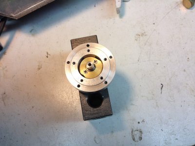
Inside the Cam Housing. Once inside the cam housing, .125 diameter ball bearings are dropped inside the cam follower holes and they will roll on the outside eccentric off of the cam. The cam followers will be "above" the ball bearings and will push the push rods.

HaloCam5.JPG

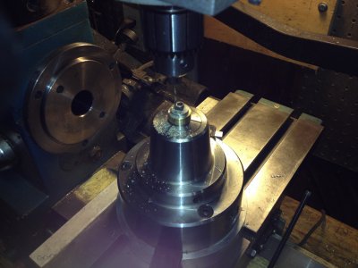
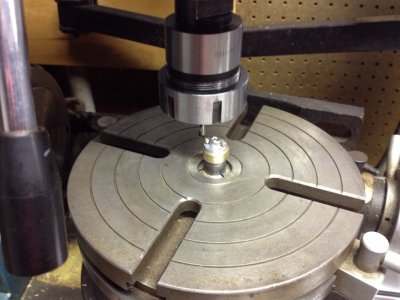
In the setup above, I have made an arbor to fit the cams. I drill through the cams with a #43 drill but NOT into the arbor. There is an aluminum washer underneath the bottom cam and I didn't drill through it. I had previously used this same setup to #50 drill and tap the 2-56 cam mounting holes in the crankshaft, and the crank pin mounting hole in the crank.

HaloCam6.JPG

I mounted the rotary table with the cam arbor in the center of it, found the center of the arbor, and set the rotary table on zero degrees. Then I drilled two #50 holes and tapped them 2-56 threads. Then I screwed the cams down onto the arbor.

Halocam7.JPG

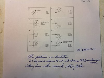
Above is the map I used to cut the eccentrics using the side of a .250" endmill.

What do you think? When I assemble it, what kind of grease do you think I should use on the cams / bearings / followers?

Take Care
Dave

HaloCam1.JPG HaloCam2.JPG HaloCam3.JPG HaloCam4.JPG HaloCam5.JPG HaloCam6.JPG Halocam7.JPG
 
Lovely work, some day maybe I'll have that kind of time. Please keep it coming.
 
I am in awe of anyone who can do this quality of work.
Thanks for sharing and I eagerly await further installments.
 
Rocker Arms for the Halo

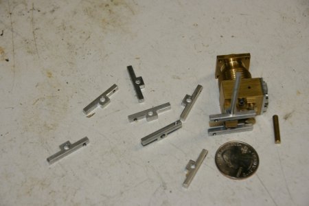
Rocker1.JPGRocker2.JPG

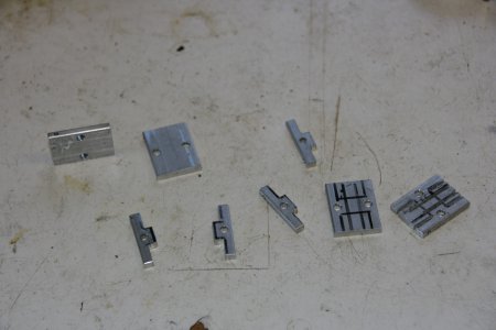
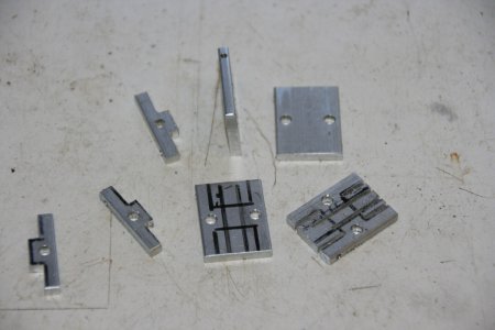
The rocker arms began life as a 1/8" x 3/4" aluminum flat extrusion. I decided to use the natural sides of the bar as the tops of the rockers. I cut them on the band saw and then milled the ends to the desired overall length.

Rocker3.JPGRocker4.JPG

I drilled the required holes in the parts first. I used a sharpy to mark the desired shape and took them to the HF band saw set up in vertical to cut them out.

Rocker5.JPG

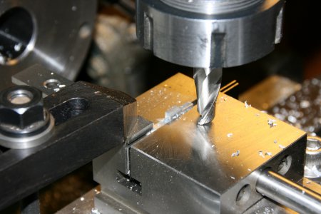
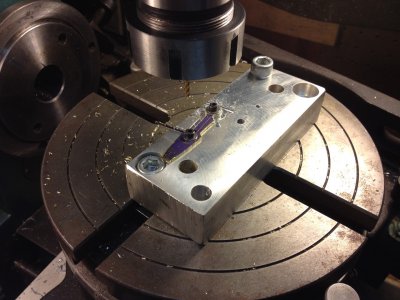
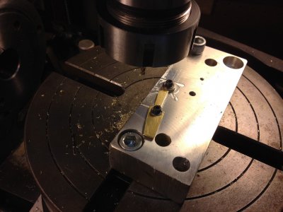
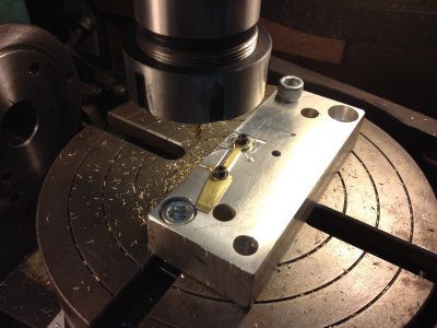
A couple passes with the milling cutter to finish the shape. De-burring the little buggers was fun, I must have dropped each one four times! Lastly I tapped the 2-56 for the socket headed cap screw that will hold the end of the push rod in the socket and allow me to adjust the valves...

IMG_3183 (Small).JPG

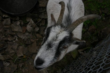
This is Rev, one of my pygmy goats.

Rocker1.JPG Rocker2.JPG Rocker3.JPG Rocker4.JPG Rocker5.JPG IMG_3183 (Small).JPG
 
I love watching posts like this one, building something with that much forethought, patients and skill is awesome.
 
Making the Halo Pistons

Well, I was back in the shop today, thank goodness.

Piston1.JPG

The pistons were made from 3/8" 360 brass round bar. One of the pistons connects to the "Master Rod" so the slot for the connecting rod is smaller than the other four pistons. In the picture above the two pistons closest to the camera have been deburred and polished. The ones in the back have not been deburred. The wrist pin is a .0625" round pin that is a press fit.

Piston2.JPG

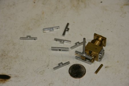
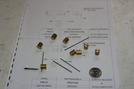
First I cut the pistons to the overall length. In the picture above, there are the piston billets, a small center drill, a #53 drill, a .0615" ream, a .061" gage pin, a .062" gage pin, and a US quarter dollar coin.

Piston3.JPG

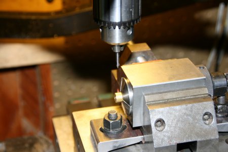
Shown above is my setup for the second operations on the pistons. I have a 3/8" 5C Collet with a collet stop in the other end, secured in a vise, mounted on the mill. The photo above shows the small center drill in the drill chuck. Each part was tightened into the collet, center drilled, drilled through with the #53 / .059" drill, then reamed with the .0615" reamer. I used the .061" gauge pin to check the GO and the .062" pin as the NOGO.


Piston4.JPG

After all the parts were drilled, I changed over to the slitting saw. I want the slot perpendicular to the hole for the wrist pin. So in the photo above I used the .061" pin and another small piece of aluminum with a .0615" hole also in it to line the piston up before tightening the collet.

Piston5.JPG

The slitting saw is .0625" thick, but with run out and what not, it cut .065" which is what the Master piston slot requires. For the other pistons, I moved the cutter up .030" from 0 center, made a pass, moved it down .030" below center and cut the second pass, changed to the next part, made a pass, moved it up, made the second pass, changed parts....

I deburred them with a jewelers file and polished them with a cloth wheel on a dremel.

Piston1.JPG Piston2.JPG Piston3.JPG Piston4.JPG Piston5.JPG
 
Halo Master Connecting Rod

Mrod1.JPG
Mrod2.JPG

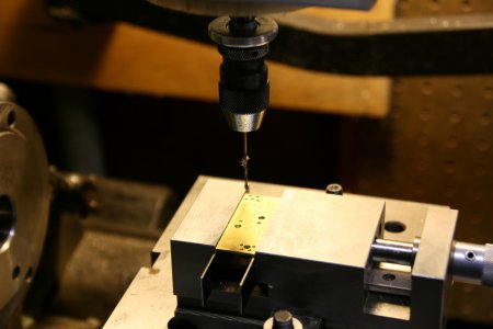
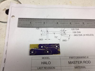
This is the Master Connecting Rod for the engine. It is connected to the crank pin on one end and the "master" piston on the other. The other four connecting rods connect to it instead of the crank. Well, this is one of the parts for this engine that seemed to require a lot of thought and twitter pating on my part about how to make it. I guess because it is so small. Then I had an epiphany that I could make it longer than it needed to be so it could be held it on both ends and then cut it down to size. It was made from a small piece of 1/16" thick Brass 3/4" x 2". There was enough material to make two and I thought I should in case I made a mistake...

Mrod3.JPG

I used my DRO and drilled the holes first using a tiny bolt circle pattern. The hole for the crank pin is reamed .126" and guess what, a 5-40 screw is a slip fit in a 1/8" hole. I drilled another hole in the material a quarter inch past the end of the part away from the hole for the wrist pin.

Mrod4.JPG

Above is a picture of the parts after drilling the holes, slapping some Dykem on them, and scribing the general shape of the part on it. This is for reference for the next steps.

Mrod5.JPG
Mrod6.JPG

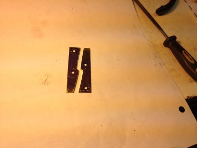
I used the band saw to saw most of the way through between the two parts and then I used a piercing saw to separate them.

Mrod7.JPG

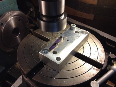
I mounted up my trusty rusty rotary table and dialed in the center of it and set it on zero degrees. Then I mounted a sacrificial piece of aluminum on top of the table. I shaved the top of the aluminum with a fly cutter because there were scars from another battle on it. I drilled and tapped a 5-40 screw hole at 0, 0 and another at x = 0 y = 1.038 for my other hold down. In the picture above I have screwed the part down and milled around the crank pin end to create that end of the part

Mrod8.JPG

Above I have milled away one side of the long skinny part of the rod.

Mrod9.JPG

In order to easily make both sides of the part a mirror of each other, I simply deburred the part a little and flipped it over and remounted it.

Mrod10.JPG

Milled off the other side. It probably took me an hour to mill the first part and literally ten minutes to do the second.

Mrod11.JPG

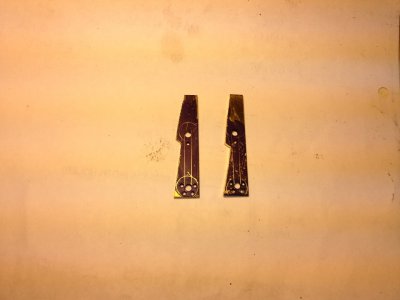
At this point the parts look like the part on the top of the above photograph. The part on the bottom is after I took it to my one inch sanding belt and shaped the pentagonal part of the crank end. I have also waylaid it with a file or two..
Next I took a hack saw and cut off the big flag that is on the left side of the photo past the wrist pin hole. Then I did the final shaping and sizing of that end of the part with the 1" sanding belt and more filing.

Mrod12.JPG

Above I have just put the part in the crank case to admire it.

I hope that you are enjoying reading this and looking at the pictures.

Thanks and Best Regards - Dave

Mrod1.JPG Mrod2.JPG Mrod3.JPG Mrod4.JPG Mrod5.JPG Mrod6.JPG Mrod7.JPG Mrod8.JPG Mrod9.JPG Mrod10.JPG Mrod11.JPG Mrod12.JPG
 
This is the part I have been longing to see . The master rod and its connecting links it seems to bring it all together.

Not long now Brian.
 
Yes, Brian, it does bring it together. I have the other 4 connecting rods cut to size, I may have them completed tomorrow. I have to finish the rocker arm shafts and make the push rods. Then I believe all the parts will be made. Oh, I just remembered, I have to design and make the stand / base to hold the completed engine. I want something so that you can look into the back of the crankcase to see the crank and connecting rods in action. And I will need an intake manifold of some kind. Also, after I get it running, I want to make a flywheel that is functional and appropriate. I'm uncertain now just how much of a flywheel it will need. I think I want a propeller for show and maybe a flywheel for go and it would be great if I can get something working for both. Of course there is probably considerable tinkering and assembly / dis-assembly to get it to run! But, it won't be long now before it is done.

Dave
 
Back
Top