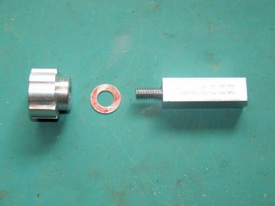
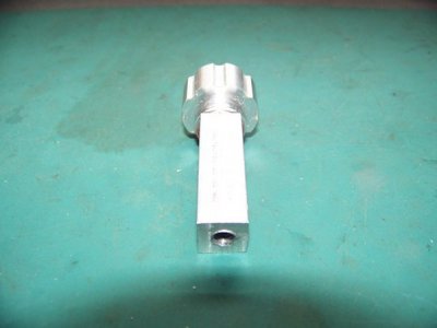
Now that I finally have some limited milling capabilities thanks to my new milling attachment for the 7x12, the first little project I wanted to do was to make some indicator holders…one for the vertical axis of the attachment itself as well as one for the lathe cross-slide. FYI, don’t look too close as I did make a few little boo-boo’s…
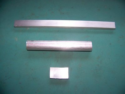
After seeing Mark_F’s gem of a holder for his cross-slide http://www.hobby-machinist.com/threads/cross-slide-indicator-holder.37113/ , I shamelessly borrowed his basic design, with a couple alterations made for my application. Raw materials were all 6061 aluminum - ¾” x ½” x 11” long flat bar, 1” round bar and a little scrap piece of ½” thick plate from the junk bin.
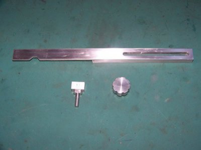
First, I milled a full depth .250” slot x 3.750” long c-t-c in one end of flat bar and then a .375” wide x .250” deep slot on top of that for indicator mount to slide in. On the other end I milled a pocket .375”wide x .500”deep x 4.750” long to fit on lathe saddle. Marked & drilled two .191” thru-holes on top w/.312” x .100” deep counterbore for low profile 10-32 SHCS’s to attach bar to saddle.
Next I made the mount between indicator and flat bar. After squaring up the scrap piece, I mounted it in the 4-jaw and turned it down to .500” for 1”, then went back and turned it down to .250” for .750”. Finally threaded the end ¼” - 20 by .500”.
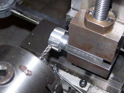
Lastly, I made the knob out of 1” diameter round bar x .750” long. Turned one end down to .650” x .250” long and drilled/tapped it ¼ - 20 x .600” deep. I don’t have a knurling tool yet, so to grip the knob I just cut 8 slots .050” deep with a 3/16” ball end mill (only ball-nosed end mill I currently have). Not very fancy, but it works.
Finished pieces (other than sanding out machine marks):
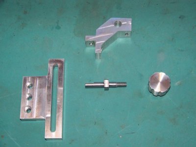
Next up was the holder for milling attachment. Pretty much the same idea again with a couple obvious differences. The goofy looking piece at top of pic mounts to the plate with vice (moveable) while the rest mount on the angle plate attached to cross-slide (fixed). Threaded piece made from ½” 1144 round bar.
Here they both are mounted and ready for action:
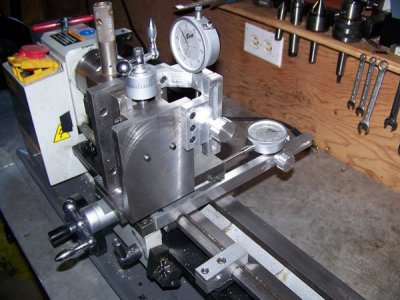
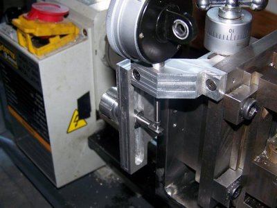
Hope you enjoy..and any criticism/suggestions are certainly welcome!

After seeing Mark_F’s gem of a holder for his cross-slide http://www.hobby-machinist.com/threads/cross-slide-indicator-holder.37113/ , I shamelessly borrowed his basic design, with a couple alterations made for my application. Raw materials were all 6061 aluminum - ¾” x ½” x 11” long flat bar, 1” round bar and a little scrap piece of ½” thick plate from the junk bin.

First, I milled a full depth .250” slot x 3.750” long c-t-c in one end of flat bar and then a .375” wide x .250” deep slot on top of that for indicator mount to slide in. On the other end I milled a pocket .375”wide x .500”deep x 4.750” long to fit on lathe saddle. Marked & drilled two .191” thru-holes on top w/.312” x .100” deep counterbore for low profile 10-32 SHCS’s to attach bar to saddle.
Next I made the mount between indicator and flat bar. After squaring up the scrap piece, I mounted it in the 4-jaw and turned it down to .500” for 1”, then went back and turned it down to .250” for .750”. Finally threaded the end ¼” - 20 by .500”.
Lastly, I made the knob out of 1” diameter round bar x .750” long. Turned one end down to .650” x .250” long and drilled/tapped it ¼ - 20 x .600” deep. I don’t have a knurling tool yet, so to grip the knob I just cut 8 slots .050” deep with a 3/16” ball end mill (only ball-nosed end mill I currently have). Not very fancy, but it works.
Finished pieces (other than sanding out machine marks):

Next up was the holder for milling attachment. Pretty much the same idea again with a couple obvious differences. The goofy looking piece at top of pic mounts to the plate with vice (moveable) while the rest mount on the angle plate attached to cross-slide (fixed). Threaded piece made from ½” 1144 round bar.

Here they both are mounted and ready for action:


Hope you enjoy..and any criticism/suggestions are certainly welcome!


 but you get there in the end, & you do it right the next time.
 Some of you more experienced fellows may read this and shake your head wondering what the heck I was thinking, but hey, welcome to my world!