- Joined
- Jun 12, 2014
- Messages
- 4,806
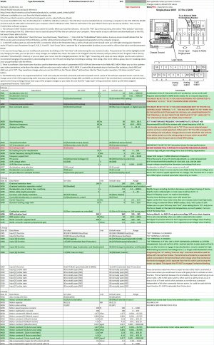
This is a review/discussion of the installation of a Hitachi WJ200 VFD and changes to the control switches on a PM1340GT lathe. The lathe was purchase as a 3 phase unit, the stock 3 phase motor was retained. The Jiuh Dah Electric (Taiwan) 2 HP motor is not inverter rated, the nameplate indicates it is 220V, 60Hz, 6.6A and turns at 1720 RPM. The motor is not large, and is a tight fit. It appears to be a Metric D90L frame, the motor housing measures ~10" in length and 7 1/4" in diameter. The stock motor shaft is an unusual spec of 3/4" by ~3". There is only 1" between the back motor fan guard and the lathe splash guard, and the motor diameter limits the belt adjustment range. Those interested in a possible inverter rated replacement motor, might look at the 2 HP Leeson True Metric D90L 169862-00 or the Marathon version 090LT17FH6326 which looks identical. Both of these have 24x50 mm shafts, so the stock pulley would need to be bored or replace it with a different one. Replacement 2 HP vector rated motors I checked where too long to fit without cutting off the rear shaft. That being said, most 2 HP inverter rated motors have a constant torque ratio of at least 10:1, and have a useable maximum RPM of 1.5-2.0X the base (60 Hz) speed for 1800 RPM models. TEFC (fan cooled motors) are limited at slow or high speeds by the fan cooling capacity. I currently use the stock motor over a VFD frequency range of 20-80Hz, so a usable lathe RPM range would be around 25-2250. Using the vector motor VFD setting , there is no cogging even at very low speeds, I am adding a digital RPM meter to provide the lathe readout speed.
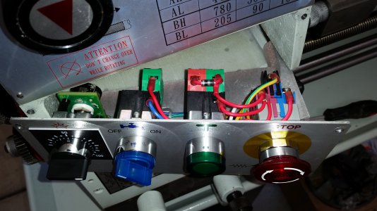
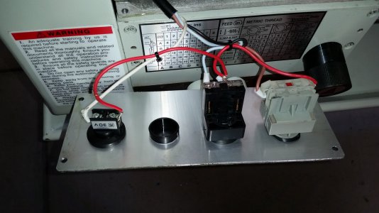
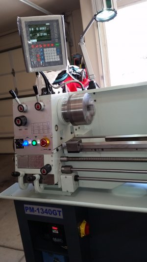
So on to adding the Hitachi WJ200 inverter. Usually I hardwire the VFD controls directly to the inverter with shielded cable, and use limiter switches and a safety stop switch. In the case of the PM1340GT, I decided to have a bit more complex switch logic with safety interlocks. The front mounted switches were all replaced with higher quality lighted units, and have multiple switch contacts needed for the interlock logic/light control. As currently configured, the coolant is operated only when the forward/reverse switch is engaged. An emergency stop, power outage or end of travel switch deactivates the forward/reverse switch until the lever switch is placed back to the stop position. The stop position deactivates the forward/reverse switch/relays, and also sends a lockout signal to the VFD to ignore all other commands. The Jog switch deactivates the other controls except the emergency stop. The system logic is reconfigurable. All a bit over the top, but adds a bit of safety and made an interesting project.
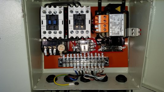
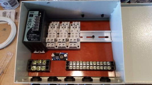
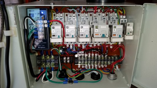
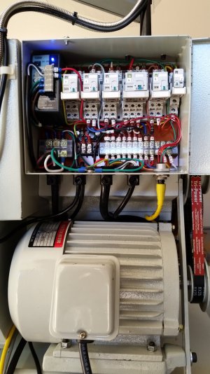
I opted to replace the stock control board and reconfigure the electrical switching system. The main board is now 1/4" Electrical grade linen phenolic, with an attached DIN rail to mount a 24VDC 100W (PWM) power supply and 24 VDC, a voltage regulator is mounted to the board to provide 7.5V to the RPM readout. I used separate relays (see picture) to control the coolant system (9), forward (3), reverse (4), main power interlock (9, ) stop (6), and jog (7) functions. These are connected in a way to provide interlocked actions as well as VFD control. These all just fit in the control box. The connection wires are connected using screw terminals, they are color coded and labeled as to function and connection. A star grounding system connects everything. All controls and cables can be quickly disconnected, relays provide LED function status to verify the operation of the mechanical switches. The stock lathe light uses a 24V 50W incandescent bulb, this was replaced with a 9W 24V LED bulb. So much cooler and whiter light with less power load. The stock AC control transformer was 24VAC, ~100W.
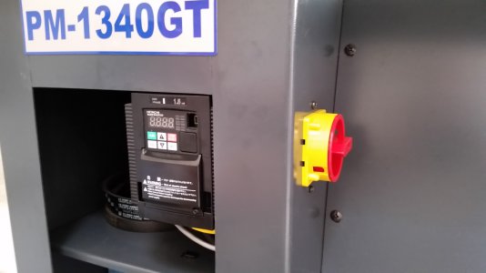
The Hitachi WJ200 Inverter is mounted in the lower cabinet using L brackets, and also mounted is 20A main power switch. Switched power is set-up to provide 120/240V for the power supply/DRO/coolant system, 240V for the VFD. All power and shielded motor/control cables are routed through watertight bulkhead fittings in the back of the cabinet. All high voltage wiring uses ringed crimps to connect to the screw terminals blocks. The VFD is easily accessible if needed. I had installed VFDs in the past, but the Hitachi (industrial grade) VFDs have a wide range of functions and was bit frustrating at first to get to work correctly. You can program these functions from the VFD control panel, but I found it much easier (after getting the software to work) to do this via a computer. The software, nor a hardcopy instruction manual was provided with the WJ200. The USB driver and Program software is available from the Hitachi web site, one must install the programming control software AND the driver software before connecting the VFD. I initially could run the program, but could not connect via the USB. If you use Windows, after the software is loaded and the VFD is on, connect the USB cable, go to Devices and Printers and make sure you are connected to the WJ200.
Hitachi software is available at no cost from their site.
http://www.hitachi-america.us/ice/in..._drives/wj200/
Software:You must first install the PDN driver first before connecting your VFD
http://www.hitachi-america.us/ice/in...pro_smm_sss_sd
Then install the ProDriveNext 2.1.1 English
http://www.hitachi-america.us/ice/in...oftware_dload/
The WJ200 needed to be programmed before it would work, the basic functions are fairly straight forward but I found running the VFD via the software reset some of the terminal functions causing the VFD to stop accepting terminal commands. In the end, I printed up the Quick Reference guide Group F, A B, C, H and P name/functions pages, and noted the changes I wanted to make. I then would make a few changes, download them to the VFD and then test the system. This way I could isolate any problems/changes. I also downloaded the Yaskawa V1000 VFD manual, which I found had a better descriptions of some of the same functions.
So far everything seems to be working according to plan with one small glitch. I use the VFD to brake the lathe, it is set to 1 second and works well up to an RPM of ~1000. Beyond that the regenerative energy trips the inverter into an overvoltage error. This is not uncommon. There are other program settings that can be used to tweak this, but there is a lot of momentum in the system at the higher speeds. I will be adding a braking resistor 50 Ohm (500-100W), and add a switch to go to a longer 2 stage deceleration program for higher RPMs.
Pictures: Old and new front panel switches; Original control board; Main linen phenolic board/Din rail; Wired control board; Wired control board with motor; Cabinet mounted VFD/power switch; Up and running.
May the force (VFD) be with you.


