Keeping The X On A Round Column Mill

Canuck75

Active User
H-M Supporter Gold Member
Joined
Jan 1, 2014
Messages
233
Two years ago I posted a thread on keeping the X on my King PDM30 by fixing the rack to the column, and attaching two tight fitting guide blocks on the head. I was getting .001" repeatability. As a method of checking I set a 1-2-3 block in the vise, edge found the X and Y, set both the DRO and lead screw dials to zero, moved the head, edge found again seeing both the lead screws and DRO rereading zero.

I recently watched a You Tube video by Cuppa Joe (Wrong Fu II) in which he used a linear brg and shaft, plates clamped to the top and bottom of the column (8.5" column C/L to shaft C/L), and replacing the hood with a 3/8" flat plate to anchor the brg relative to the head. As a check of the resulting accuracy, he set DI against the extended quill and moved the head up and down. His results were impressive to > .001". Moreover, because of the sturdy design, the head doesn't wiggle when being moved.

Today I decided to re-test my mill the same way as Cuppa Joe did and have attached a video to show the results. I know the distance between the guide blocks and the column C/L vs the distance between the column C/L and the quill C/L is not ideal for control, but it seems to work well enough. Cuppa Joe's mill has a split head casting and two clamping bolts, as mine does, but in his case, it doesn't seem to matter how you retighten the bolts. On mine it does, the top one has to be tightened first. In the video you can see how much the head comes adrift after unclamping and if you don't fully retighten the top bolt first it will be off, as it was in one case in the video. Just the interaction between the rack and the split head as it comes back together I believe.

Anyways, it was a bit of relief to see that the setup is still accurate.

Canuck75
 

Attachments

  • MVI_7714.mp4
    11.2 MB · Views: 355
I have an Excel EC 30B Mill/drill and have been pondering this round column x y axis issue. I have read numerous threads about possible solutions and all seem to entail a fair amount of precision machining, fabrication and alignment. What I have been thinking about doing is scribing a line down the column parallel to the column axis coupled with a witness mark(s) on the head. When you move the head all you would have to do is realign the witness mark with the scribed line and you should be good to go. This seems like a really simple solution. I am I missing something here?

Chuck
 
The problem with that is the witness marks will get you kinda close, sorta. :cautious: You still have to dial in the last few thousandths. Consider the distance from the column to the spindle, a very small amount relative movement at the column translates into a large movement at the spindle.
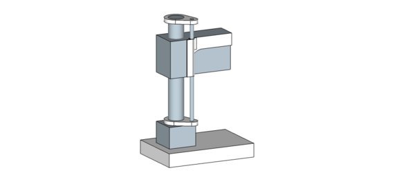

 
Best simple solution we can come up with is a simple post and base plate.

Imagine a chunk of good round stock welded or attached to a flat chunk of steel with one hole in it.

This must be square to table so a machinists square is also needed to verify.

When needed this is bolted to table and verified square to table.

Method to measure distance to spindle depends on your style.

Adjust z then place spindle distance same distance as before and remove tool if needed.

Repeatable to accuracy of tooling and build.

Sent from my SAMSUNG-SGH-I337Z using Tapatalk
 
Canuck75
I am wondering just how hard it was to attach the rail to the column. I can chuck the column up in my lathe using my 8" 4 jaw chuck and a 6" center that I have held in the steady rest. I could then use the carriage with the dial indicator on the compound to keep everything lined up. But I worry about everything staying line up as I drill the holes by hand. How did you clamp the rail to the column as you went along. Do you use large hose clamps? What were some the problems that you had to overcome to do this?
Chuck
 
I have also been playing around with having a separate round 1 inch column as shown in some of the threads about solving this problem. One of my concerns is keeping everything in alignment and the rigidity. I took rough measurements of my drill/mill and 3d modeled it in Google Sketchup. I then modeled a 1 inch column held fairly close the the head. Jpeg's of the models are attached. The head of my drill/mill is wider at the back than the front and there is a 1 inch step in the casting where the width changes. A bushing would fit nicely in this step.
IMHO which could be way out in left field I think that one long bushing would be more rigid and easier to align than two bushings spaced several inches apart. Boring a long bushing will likely have some taper to it resulting in play between the bushing and the 1 inch column. My machining background and experience is basically zilch. But I have a lot of experience working with fiberglass cloth and epoxy or polyester resins. One thing that I have done in the past when needing a tube to fit tightly to a shaft is to wrap the shaft with fiberglass cloth and resin. You get a tube that precisely fits the shaft. You better hope that the shaft is straight and round because if it's not you won't get the tube off the shaft. Once the tube is made you hold it in place and apply more cloth and resin to mold the tube in place.
To make the inside of the tube harder and less susceptible to wear you can add powdered bronze or aluminum to the resin.
Getting back to my drill/mill I would assemble everything making sure that the 1 inch column is in alignment with the column on the drill/mill and then I would apply more cloth and resin to mold the tube to fit the step in the head casting and have some tabs that you could drill for fasteners to hold the tube in place. I would end up with a bushing that precisely aligns the head to the 1 inch column.
What do you guys think of this solution to the X axis problem.

mill.jpg

x axis assembly.jpg

bearing.jpg
 
Canuck75
I am wondering just how hard it was to attach the rail to the column. I can chuck the column up in my lathe using my 8" 4 jaw chuck and a 6" center that I have held in the steady rest. I could then use the carriage with the dial indicator on the compound to keep everything lined up. But I worry about everything staying line up as I drill the holes by hand. How did you clamp the rail to the column as you went along. Do you use large hose clamps? What were some the problems that you had to overcome to do this?
Chuck

mickri,-

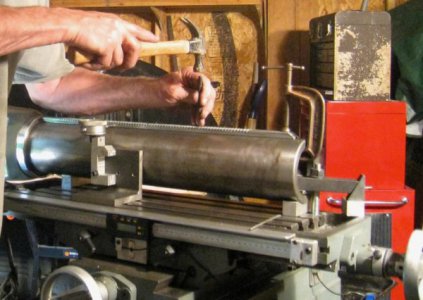
What I did was to lay the column on two v-blocks on the mill table with the rack topside by eyeball, then strap clamped the top of the column to the table. This kept it secure and the angle plate holding the DI is on a flat parallel; and smooth surface. Then, as I mentioned in the original thread, I predrilled the rack for the 1/8' roll pins in the drill press (as amany as you want), and drilled the top and bottom for FSHCs. I started by anchoring the bottom of the rack to the column with a FSHC. I then set up the angle plate with the DI attached so the angle plate runs along the side of the column and the DI runs along the side of the rack. The angle plate with the DI attached running against the column is what accurately confirms the alignment of the rack to the column centreline. Make sure the angle plate runs smoothly on whatever flat surface you are using. As I progressed up the column making sure the rack was at zero on the DI, I held the top of the rack to column with a c-clamp, drilled the roll pin hole through the column and drove home the roll pin. Move up to the next roll pin hole, make sure the DI again reads zero(warp the rack a little sideways if not), reclamp the rack at the top, recheck the DI, drill for the roll pin and install. Repeat until you are at the top. If you have done everything correctly the rack is now perfectly parallel to the column centreline and fixed firmly (forgive the use of the small claw hammer - it was just handy). The top SHCS finished the job.

Hope this helps.
Canuck75

IMG_5659.jpg
 
Last edited:
I have also been playing around with having a separate round 1 inch column as shown in some of the threads about solving this problem. One of my concerns is keeping everything in alignment and the rigidity. I took rough measurements of my drill/mill and 3d modeled it in Google Sketchup. I then modeled a 1 inch column held fairly close the the head. Jpeg's of the models are attached. The head of my drill/mill is wider at the back than the front and there is a 1 inch step in the casting where the width changes. A bushing would fit nicely in this step.
IMHO which could be way out in left field I think that one long bushing would be more rigid and easier to align than two bushings spaced several inches apart. Boring a long bushing will likely have some taper to it resulting in play between the bushing and the 1 inch column. My machining background and experience is basically zilch. But I have a lot of experience working with fiberglass cloth and epoxy or polyester resins. One thing that I have done in the past when needing a tube to fit tightly to a shaft is to wrap the shaft with fiberglass cloth and resin. You get a tube that precisely fits the shaft. You better hope that the shaft is straight and round because if it's not you won't get the tube off the shaft. Once the tube is made you hold it in place and apply more cloth and resin to mold the tube in place.
To make the inside of the tube harder and less susceptible to wear you can add powdered bronze or aluminum to the resin.
Getting back to my drill/mill I would assemble everything making sure that the 1 inch column is in alignment with the column on the drill/mill and then I would apply more cloth and resin to mold the tube to fit the step in the head casting and have some tabs that you could drill for fasteners to hold the tube in place. I would end up with a bushing that precisely aligns the head to the 1 inch column.
What do you guys think of this solution to the X axis problem.


mickri,-

I have continued to follow solutions to "keeping the X" and have seen the kind of solution you are suggesting but using a shaft and a linear bearing. All these solutions have merit in one way or another. The arms and linear bearing idea is rigid and accurate once it is lined up. Something to think about is that the "arms" might interfere with the hood or require it to be removed altogether. If they are out to the right they may restrict how high you can raise the head because the idler pulley may run into the top arm. So, lots to consider. I don't know anything about fibreglass but your ideas sound interesting.

Try and view Cuppa Joe's "Wrong Fu 1" and "Wrong Fu 11" videos on You Tube using arms/shaft/linear bearing as a solution.

Hope other H-M members way in on this.

Canuck75
 
Last edited:
I have watched his videos and like how he attached his bushing to the side of the head. That is what gave me the idea to see if I could attach my bushing to the side of the head on my mill/drill. In my proposal the upper arm would interfere with the top of the hood. If my rough dimensions are accurate I would only need to cut a hole in the bottom of the hood for the 1 inch column and remove a small portion of the upper hood piece to clear the upper arm.
I think that your method of attaching the rack to the column is the simplest and most elegant solution if your can keep the rack lined up. I will be taking the head off of my column this week. The head does not move smoothly went lowering the head and I think that the gear that meshes with the rack has a broken tooth.

Chuck
 
mickri,-

As I said, lots of things to consider. On mine the control "arm" is from the column C/L to the C/L of the rack or approx 3". This control 'arm" is then attempting to keep the accuracy of the "arm" between the column C/L and the quill C/L of about 8". It would be nice if it was the other way around, the big "arm" controlling the little "arm", but this is not to be in my setup. However, considering it works very well, was cheap, is actually accurate, repeatable, and keeps the esthetics of my machine, it is therefore fine for my purpose and needs.

If you are going to make a better system consider that "arm" question. Keeping your linear bushing close to the head won't give you the control or rigidity during head movement that placing the bushing futher away will. Cuppa Joe uses "arms" about equal length thus very rigid.

Anyways, the fun is in making something of your own design and seeing it work in the end.

Good luck and happy machining!
 
Back
Top