- Joined
- May 3, 2020
- Messages
- 229
(Some of this was posted on Practical Machinist but I eventually figured out that those guys are more serious than I am. So updates will only be posted here.)
Purchased a small horizontal mill recently. It's labeled "A V Carrol" and . I'm getting it ready to make chips. It was fairly cheap but it came with quite a few issues, including lever-feed on the x- and z-axis. There's still flaking on the ways, which is nice to see. The x-axis is a bit worn but I can live with it.
Decided to get the arbor off. Partly to figure out how it all goes together, partly because I want to make another arbor for 1-1/4 cutters. Eventually I figured out that there's a drawbar that was bottomed out in the threads of the arbor but there was still about 1/16 end play. I'll add another spacer when I put it all back together.
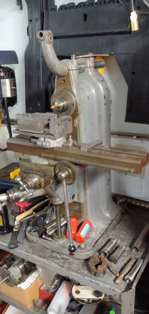
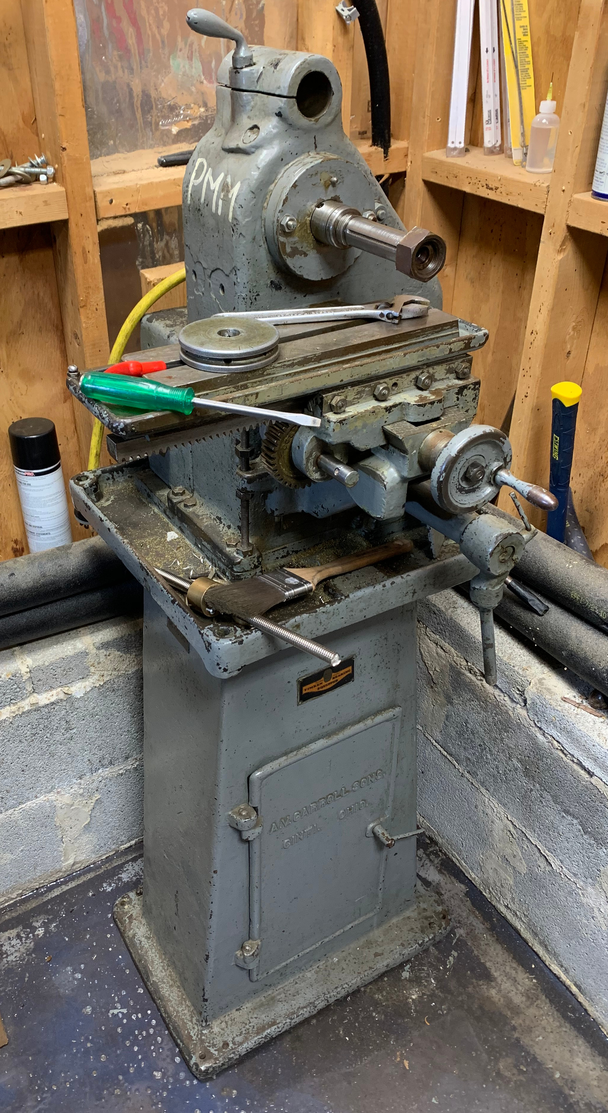
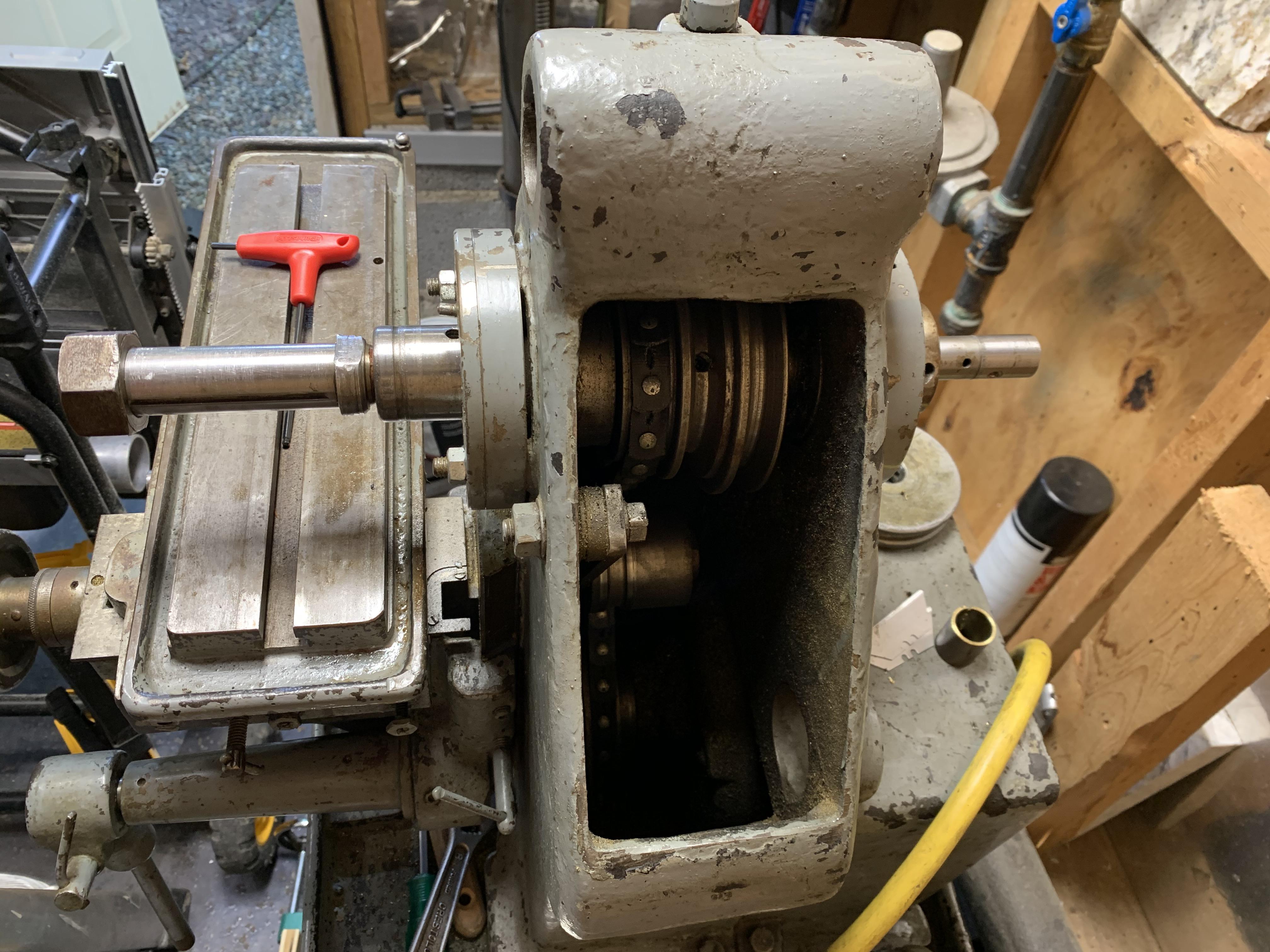
Here's the starting point, the mill in all its dirty factory-use glory. It's one of those small single-operation type mills for small parts, so the table is about counter height. It's a lot smaller than I expected, which is perfect because the shop space is about 50 sq-ft and there's already a 9x20 lathe and a drill press in there.
Here's both sides views of the spindle.
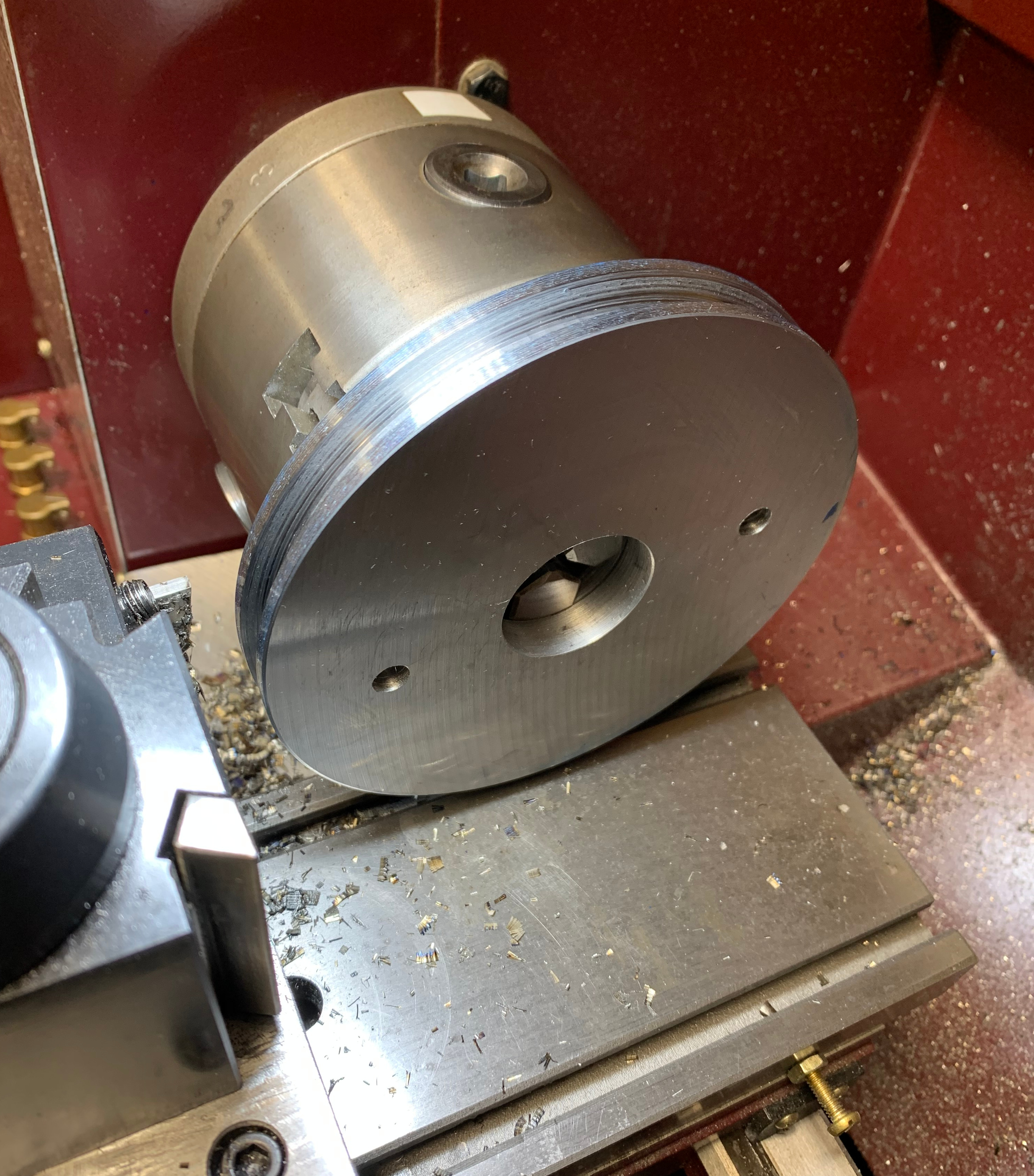
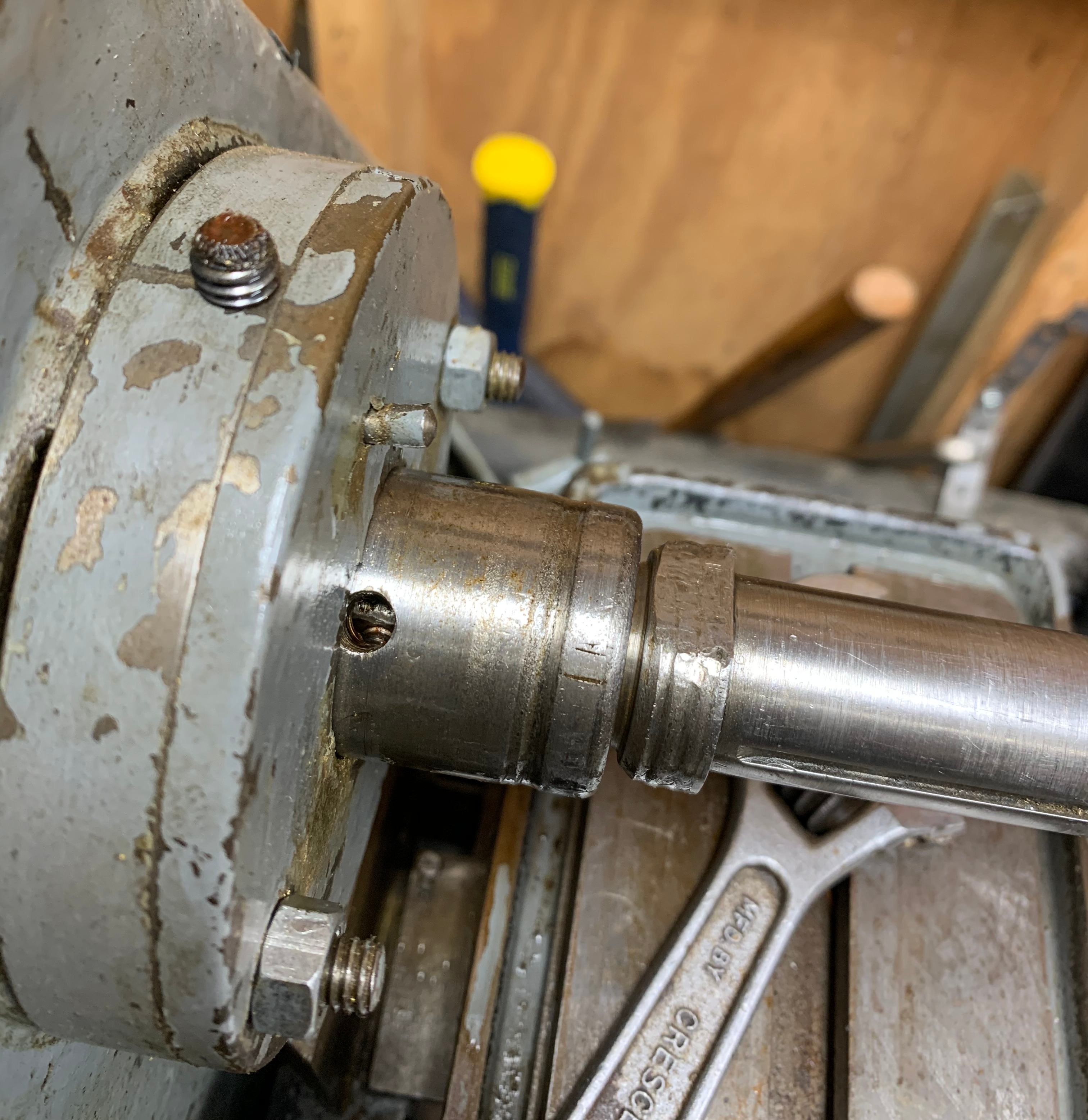
Closer view of the working end of the arbor. Note the keyway is not lined up with the set screw hole because I was messing with it. There's a matching flat on the arbor. The bearing is mounted in this little cylindrical mount/enclosure. It's a tapered roller bearing that's tensioned from the back, so the bearing assembly is sealed by that cover but the cover is held on with t-slot nuts---the screws sticking out aren't studs going back to the main casting. The bearing enclosure bears against the main casting and is connected with grub screws. I might add some 1/8 pins because there's quite a lot of play in the shaft, even after pre-loading the bearings.
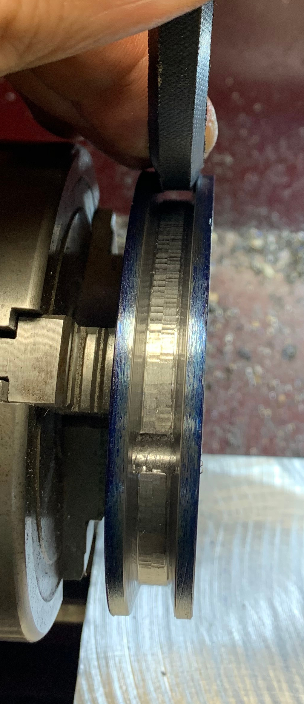
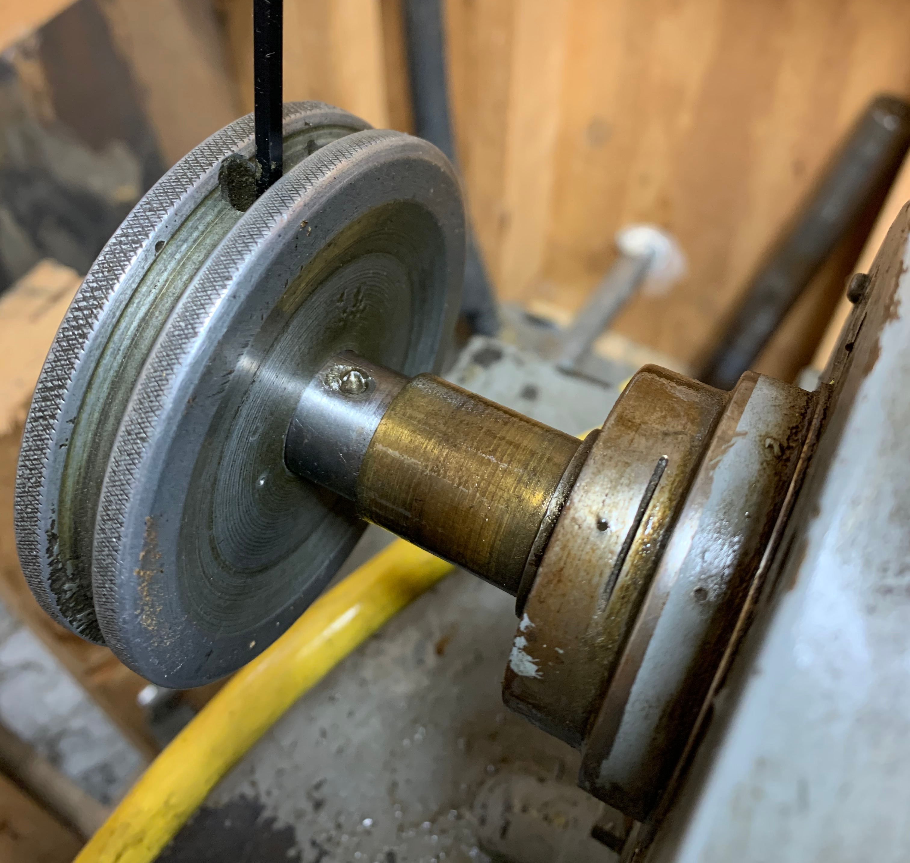
Closer view of back end of arbor. The arbor has some damage from the set screw but it's a fairly thin-walled tube at this point so it's more of a dent, no burrs that I could feel with a stone. The handwheel came off without trouble.
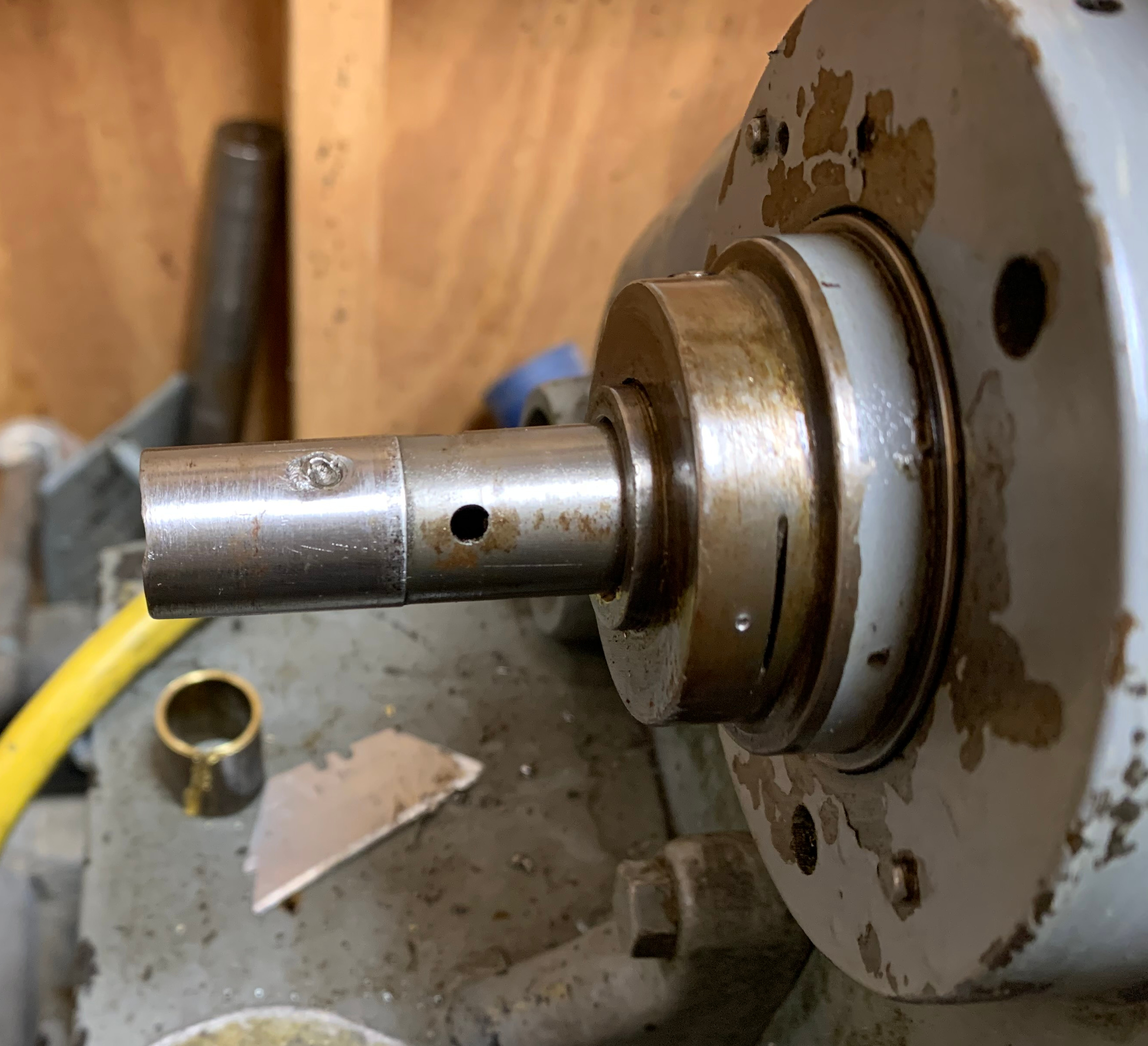
Not sure about that groove in the drawbar. On the right side, you can see the driven axis, which is a threaded 1-1/8 tube. There's a tapered roller bearing in there and the big lump there (first 2 steps) is a retaining/tensioning nut with fairly fine threads with a heavy bushing (3rd step) that transfers compression from the nut to the inner cone of the bearing . When I removed all those parts, the arbor still wouldn't come out.
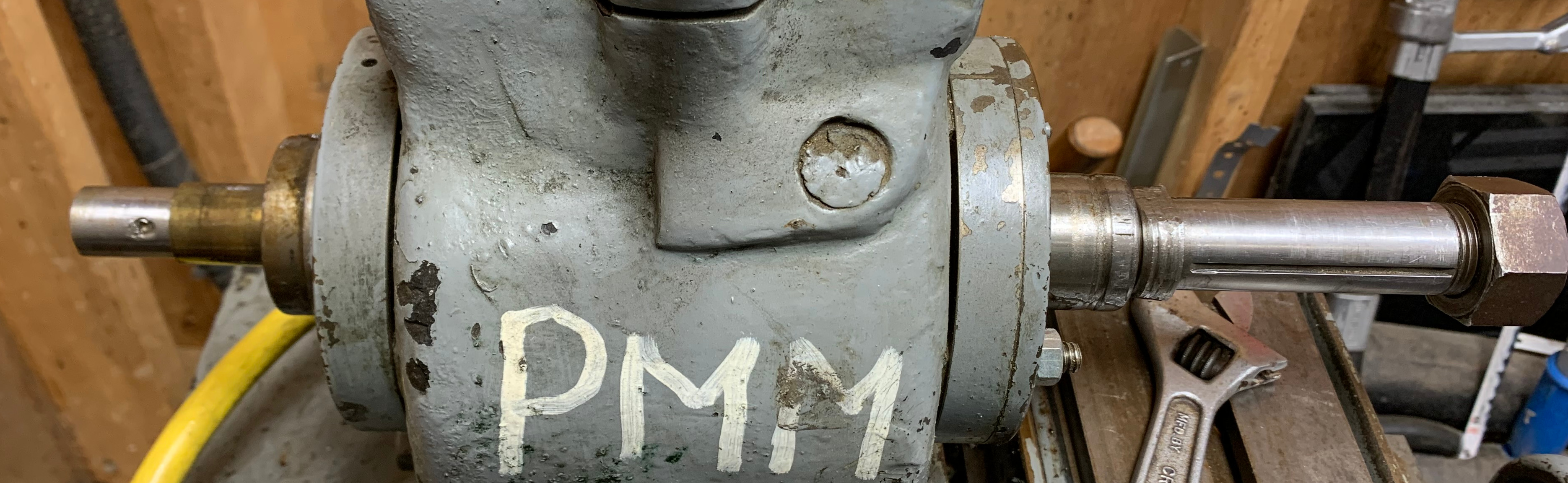
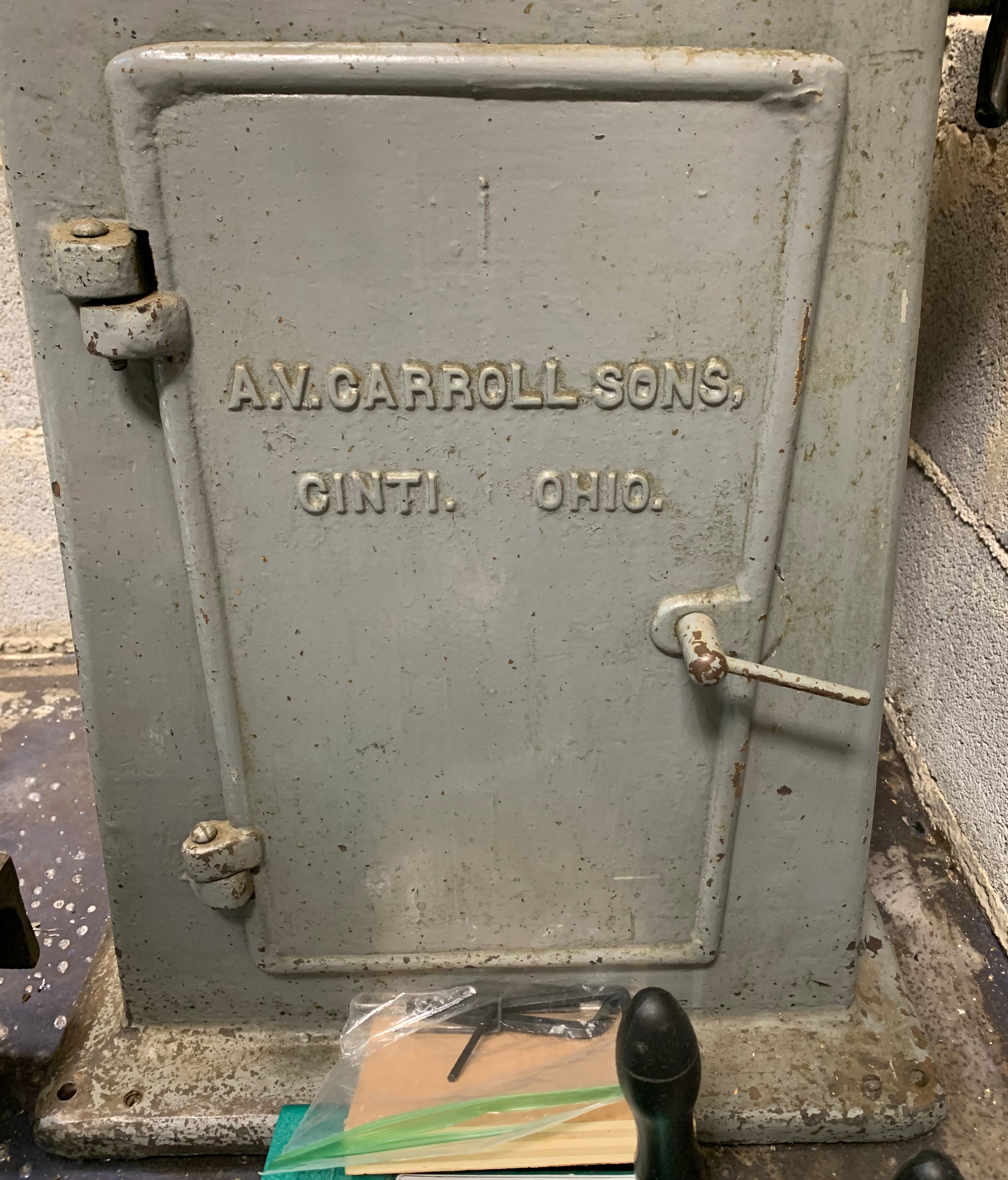
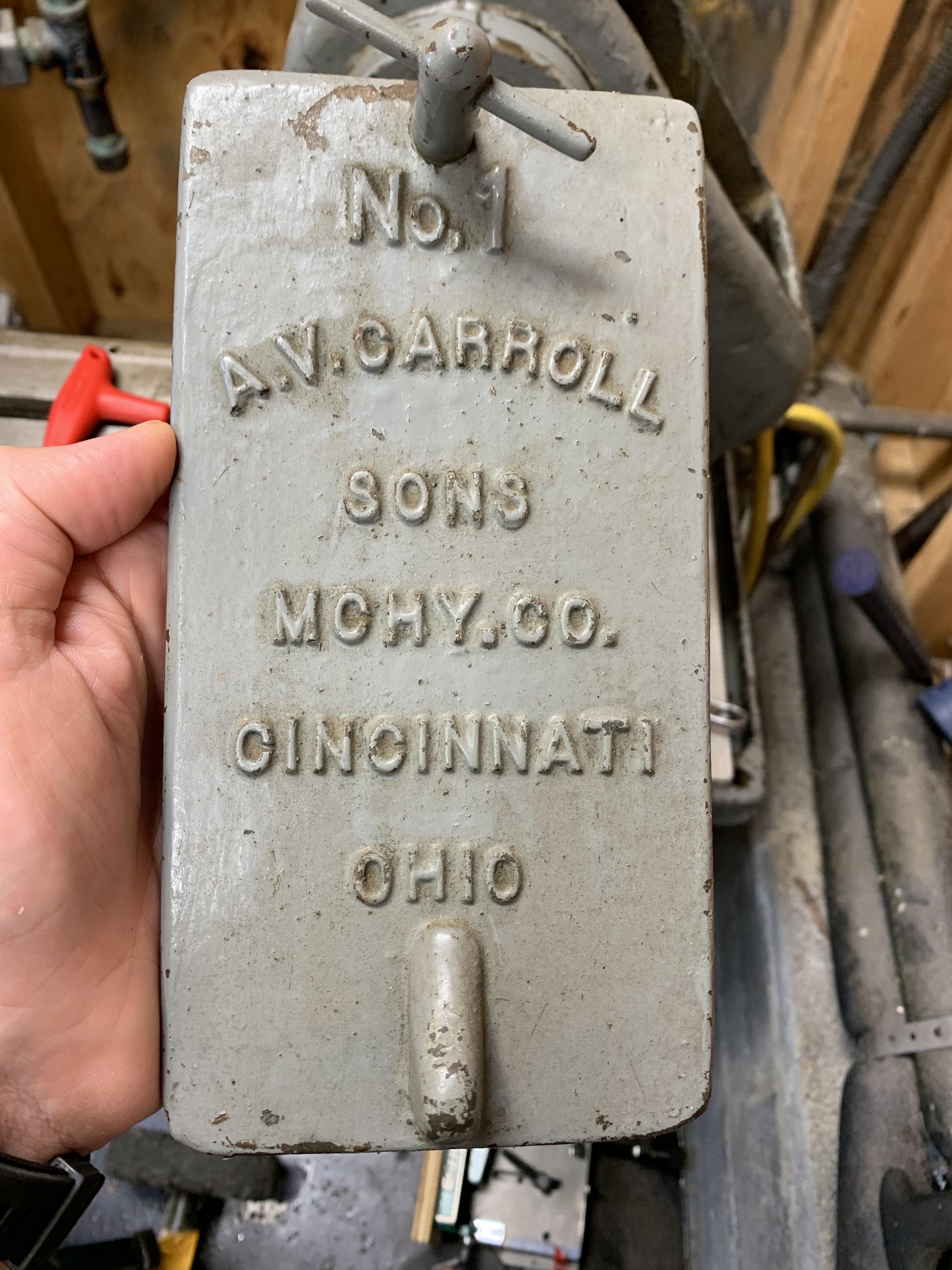
Here are images of the make/model. I haven't been able to find information about anything other than lathes that were produced by A V Carroll. I could have sworn there was another thread I started back when I was in rigging mode... Anyway, someone pointed out that machinery companies sometimes re-sell models that they don't directly produce, for business reasons. I noticed that the base is fairly generic and the only other place the manufacturer's name appears is a removable cover---easy to re-brand. So if anyone recognizes the castings, I'd be glad to know more about the manufacturer. It would be so great if I could find another arbor.
The plan... It's too much, as usual. But I'll start with the most important things.
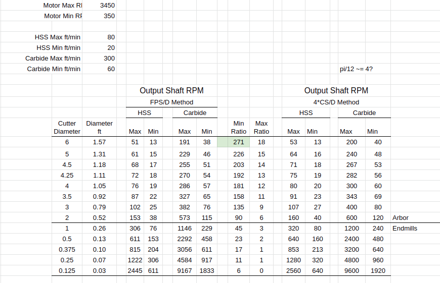
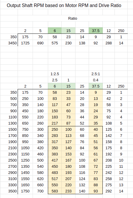
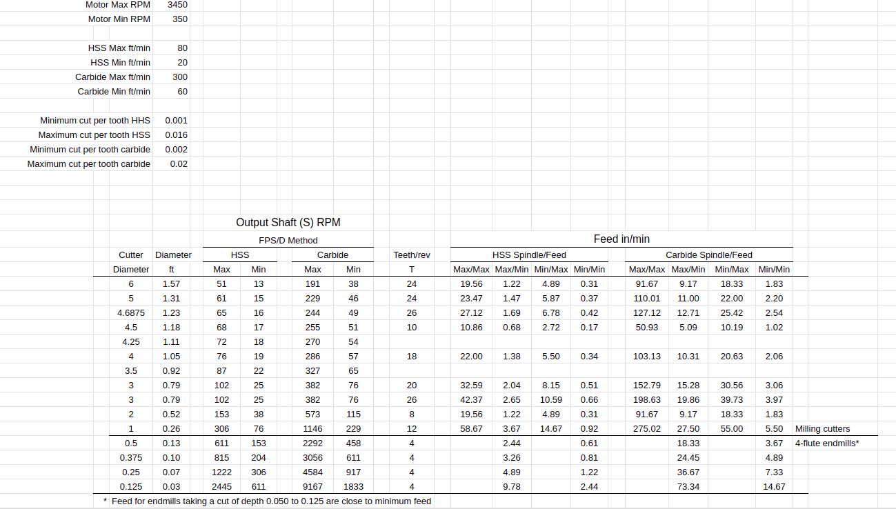
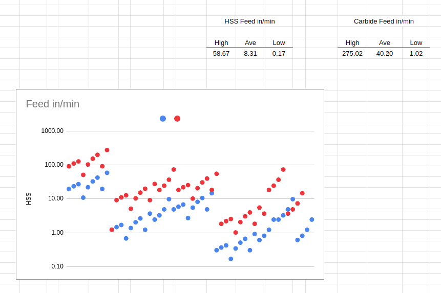
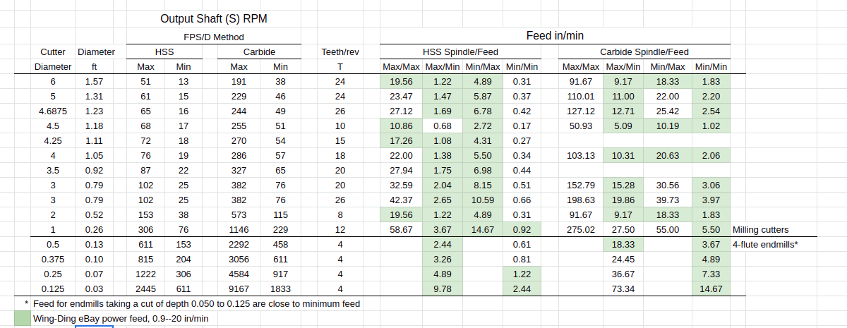
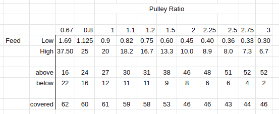
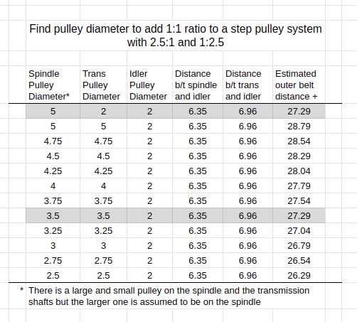
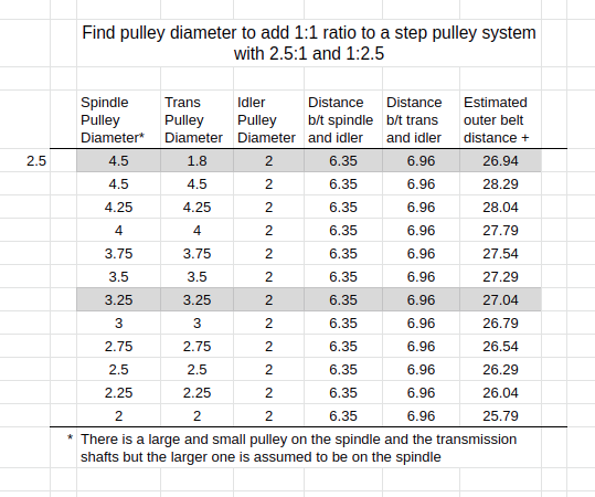
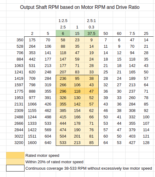
First, I need to re-power the mill. It's running 1:1 with a 1750-RPM induction motor, which is 20-30 times too fast. With a 3" HSS cutter, I need 25-100 RPM to hit reasonable feed rates (20-80 SFM for annealed low-carbon steel, according to my non-machinist reading of the 24th edition handbook). I might use some carbide cutters, so I knew I would need a high and low range. I would love to use a variable-drive type system but I just don't have the chops for that yet. So I'm falling back on a variable speed electric motor. I made a spreadsheet and figured I would need a 1:5 and a 1:10 reduction to get in the ballpark. Those ratios are pretty large and on the verge of impractical for v-belts, especially with the space constraints. Eventually, mostly by luck, I figured out that a 1:15 gearbox and a pair of pulley ratios (1:2.5 and 2.5:1 would be good. Also, I want the 1:15, so I can run the motor at half speed or more. I should be able to do it with 1 belt, switching it between 3 sets of pulleys. I tried to find ready-made stuff but for 1-1/8 bore with keyway, finding a step pulley with 5", 2" and whatever 1:1 is for the same belt length, that's about impossible. Plus, a 5" pulley may not quite fit. It's hard to know because the casting is rough and I don't know how to measure it properly. I think I'll buy blanks at McMaster, bore 1 of them, and do a trial fit. If I need to make it smaller to fit, I can adjust the 2" pulley smaller, too. For 3L belts, a 2" pulley (or a little less) should be OK. I have a 1-1/2 pulley for 3L sitting on my desk. It's extreme but possible. So that's the plan. Got a planetary gearbox on the way from Apex Dynamics (AB115) and materials for the pulleys and idlers will be here in a few days.
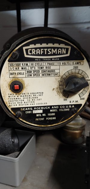
For the motor, I'll start with a sewing machine "servo" which is cheap and maybe works. There's a maximum speed dial (350-3500 RPM) and there's a pedal input with brake. No specs, though. I took it apart to figure out what was going on. The motor is brushed. Sewing machines need good torque at low speed so it's probably a series-wound dc motor. There's different speed control methods and I have no idea what it has. There is a switch to change direction and the throttle (pedal input) is a hall sensor. I did some stall-speed torque testing to convince myself that this wasn't a fools errand. I noticed that when the maximum speed was set low, torque was low. So I think I'll set it on maximum and use the throttle to set the speed. I'd like to mount the various controls remotely so I can operate the machine from the front and with a minimum of fuss.
After the mill is re-powered, I'll need to address the x- and z-axes, which were lever operated. It's a good system but a rack-and-pinion situation won't work for me. I want power x feed and finer control of z motion. The x-axis will be fairly easy to switch over to a 1/2-10 acme screw. The z-axis... It's a little harder to imagine. There are features on the castings (pan and knee) that seem perfect for installing a lead screw. So maybe it won't be so hard. Haha. Who am I kidding?
Purchased a small horizontal mill recently. It's labeled "A V Carrol" and . I'm getting it ready to make chips. It was fairly cheap but it came with quite a few issues, including lever-feed on the x- and z-axis. There's still flaking on the ways, which is nice to see. The x-axis is a bit worn but I can live with it.
Decided to get the arbor off. Partly to figure out how it all goes together, partly because I want to make another arbor for 1-1/4 cutters. Eventually I figured out that there's a drawbar that was bottomed out in the threads of the arbor but there was still about 1/16 end play. I'll add another spacer when I put it all back together.
Here's the starting point, the mill in all its dirty factory-use glory. It's one of those small single-operation type mills for small parts, so the table is about counter height. It's a lot smaller than I expected, which is perfect because the shop space is about 50 sq-ft and there's already a 9x20 lathe and a drill press in there.
Here's both sides views of the spindle.
Closer view of the working end of the arbor. Note the keyway is not lined up with the set screw hole because I was messing with it. There's a matching flat on the arbor. The bearing is mounted in this little cylindrical mount/enclosure. It's a tapered roller bearing that's tensioned from the back, so the bearing assembly is sealed by that cover but the cover is held on with t-slot nuts---the screws sticking out aren't studs going back to the main casting. The bearing enclosure bears against the main casting and is connected with grub screws. I might add some 1/8 pins because there's quite a lot of play in the shaft, even after pre-loading the bearings.
Closer view of back end of arbor. The arbor has some damage from the set screw but it's a fairly thin-walled tube at this point so it's more of a dent, no burrs that I could feel with a stone. The handwheel came off without trouble.
Not sure about that groove in the drawbar. On the right side, you can see the driven axis, which is a threaded 1-1/8 tube. There's a tapered roller bearing in there and the big lump there (first 2 steps) is a retaining/tensioning nut with fairly fine threads with a heavy bushing (3rd step) that transfers compression from the nut to the inner cone of the bearing . When I removed all those parts, the arbor still wouldn't come out.
Here are images of the make/model. I haven't been able to find information about anything other than lathes that were produced by A V Carroll. I could have sworn there was another thread I started back when I was in rigging mode... Anyway, someone pointed out that machinery companies sometimes re-sell models that they don't directly produce, for business reasons. I noticed that the base is fairly generic and the only other place the manufacturer's name appears is a removable cover---easy to re-brand. So if anyone recognizes the castings, I'd be glad to know more about the manufacturer. It would be so great if I could find another arbor.
The plan... It's too much, as usual. But I'll start with the most important things.
First, I need to re-power the mill. It's running 1:1 with a 1750-RPM induction motor, which is 20-30 times too fast. With a 3" HSS cutter, I need 25-100 RPM to hit reasonable feed rates (20-80 SFM for annealed low-carbon steel, according to my non-machinist reading of the 24th edition handbook). I might use some carbide cutters, so I knew I would need a high and low range. I would love to use a variable-drive type system but I just don't have the chops for that yet. So I'm falling back on a variable speed electric motor. I made a spreadsheet and figured I would need a 1:5 and a 1:10 reduction to get in the ballpark. Those ratios are pretty large and on the verge of impractical for v-belts, especially with the space constraints. Eventually, mostly by luck, I figured out that a 1:15 gearbox and a pair of pulley ratios (1:2.5 and 2.5:1 would be good. Also, I want the 1:15, so I can run the motor at half speed or more. I should be able to do it with 1 belt, switching it between 3 sets of pulleys. I tried to find ready-made stuff but for 1-1/8 bore with keyway, finding a step pulley with 5", 2" and whatever 1:1 is for the same belt length, that's about impossible. Plus, a 5" pulley may not quite fit. It's hard to know because the casting is rough and I don't know how to measure it properly. I think I'll buy blanks at McMaster, bore 1 of them, and do a trial fit. If I need to make it smaller to fit, I can adjust the 2" pulley smaller, too. For 3L belts, a 2" pulley (or a little less) should be OK. I have a 1-1/2 pulley for 3L sitting on my desk. It's extreme but possible. So that's the plan. Got a planetary gearbox on the way from Apex Dynamics (AB115) and materials for the pulleys and idlers will be here in a few days.
For the motor, I'll start with a sewing machine "servo" which is cheap and maybe works. There's a maximum speed dial (350-3500 RPM) and there's a pedal input with brake. No specs, though. I took it apart to figure out what was going on. The motor is brushed. Sewing machines need good torque at low speed so it's probably a series-wound dc motor. There's different speed control methods and I have no idea what it has. There is a switch to change direction and the throttle (pedal input) is a hall sensor. I did some stall-speed torque testing to convince myself that this wasn't a fools errand. I noticed that when the maximum speed was set low, torque was low. So I think I'll set it on maximum and use the throttle to set the speed. I'd like to mount the various controls remotely so I can operate the machine from the front and with a minimum of fuss.
After the mill is re-powered, I'll need to address the x- and z-axes, which were lever operated. It's a good system but a rack-and-pinion situation won't work for me. I want power x feed and finer control of z motion. The x-axis will be fairly easy to switch over to a 1/2-10 acme screw. The z-axis... It's a little harder to imagine. There are features on the castings (pan and knee) that seem perfect for installing a lead screw. So maybe it won't be so hard. Haha. Who am I kidding?