Kevin - A V Carroll Horizontal Mill Rebuild

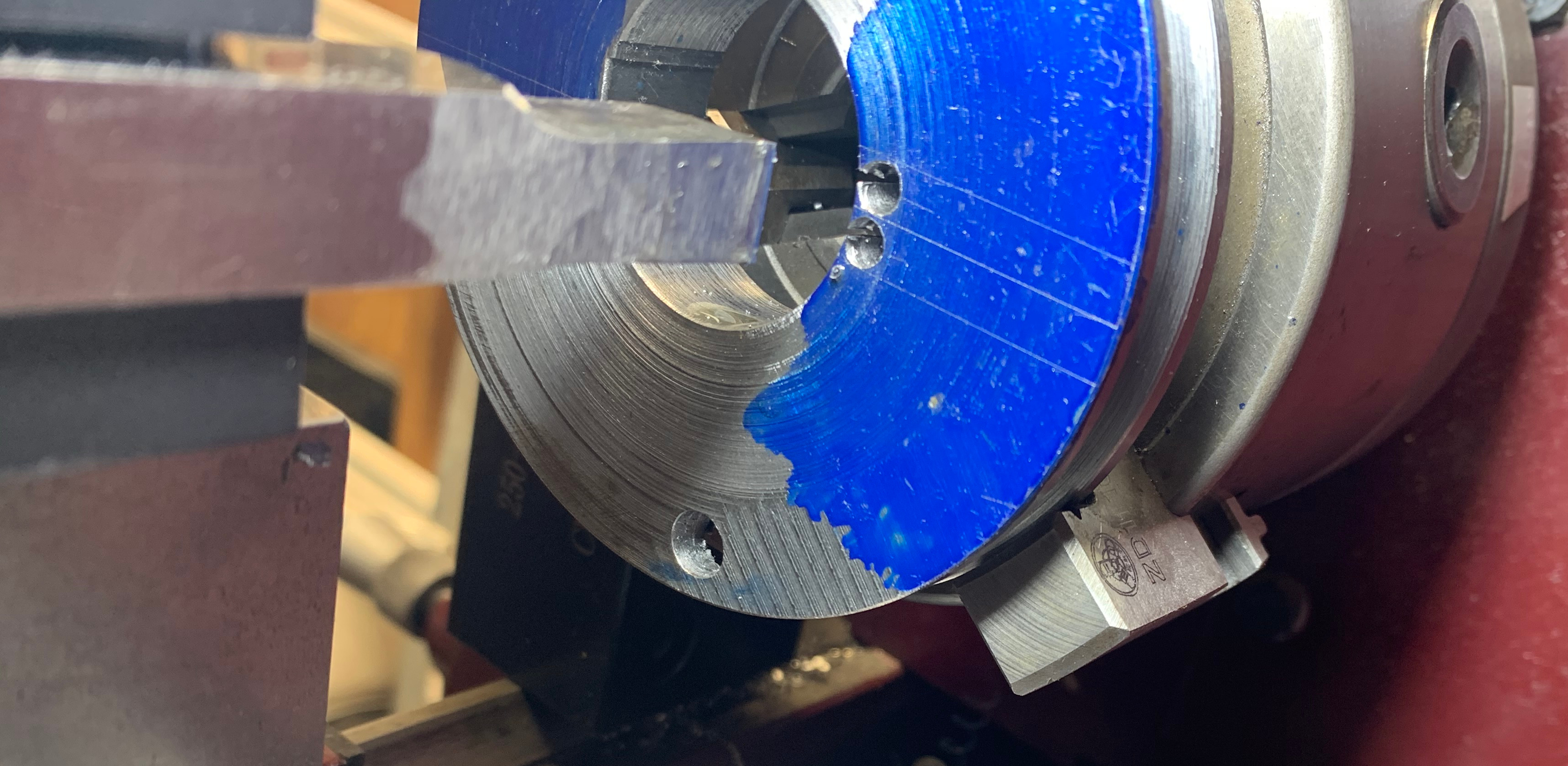
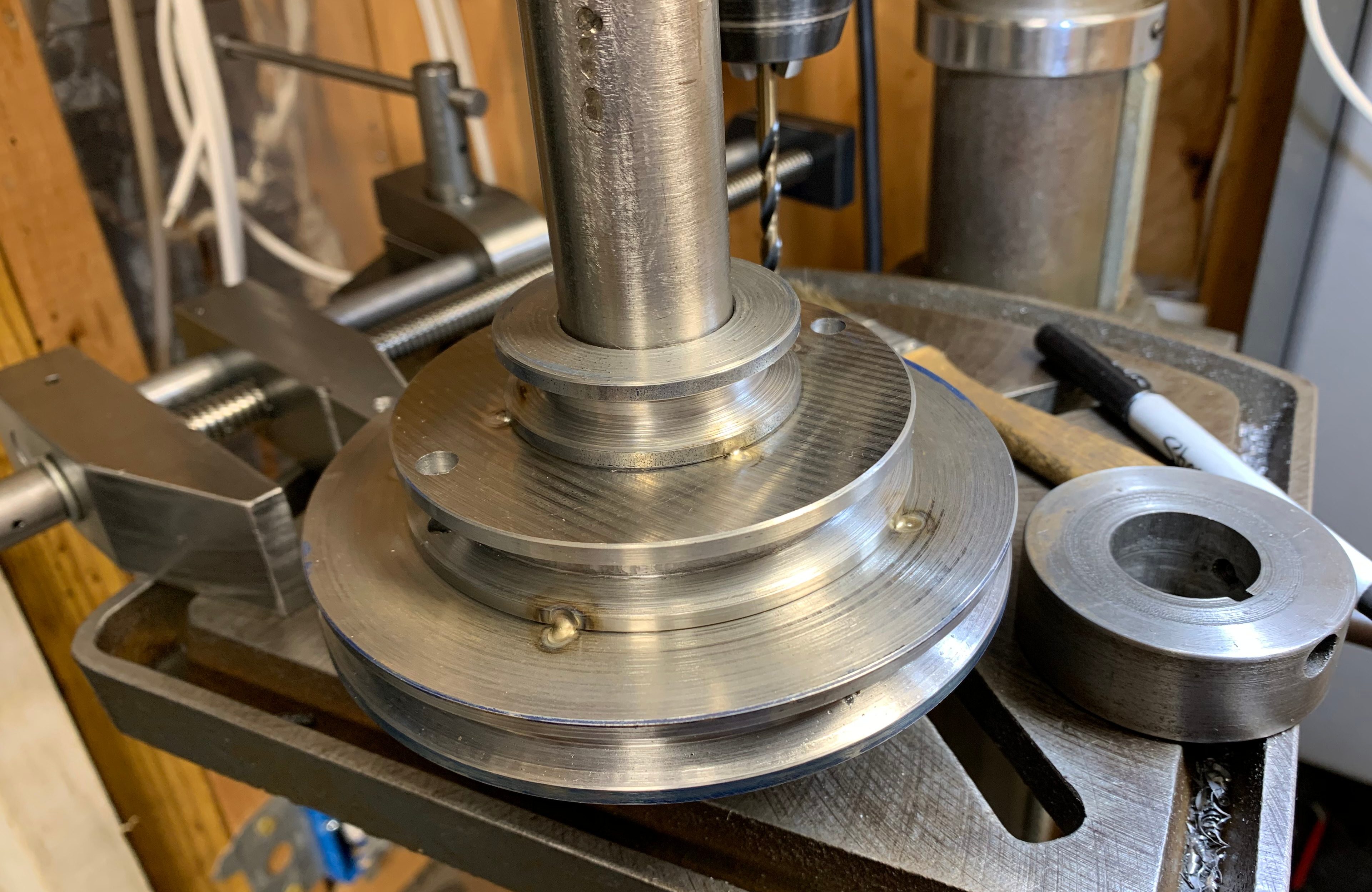
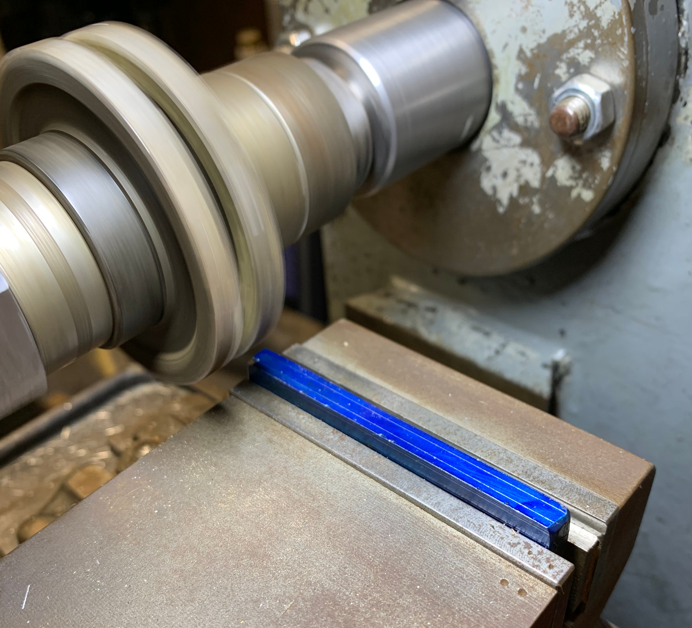
The pulleys with 1.125" ID wouldn't fit on the jaws of my chuck. Was thinking of making a mandrel. Instead, I turned down the jaws of the chuck about 0.010". I know, it's terrible practice and just shouldn't be done but it saved me so much time. The jaws were reasonably hard so I turned the chuck by hand and used a brazed carbide cutter.

The pulleys are bored and the V is cut. Took forever. Probably 8 hours for the first 3, including all problems solved along the way. The second set and the idler triple pulley took more like 4 hours.

Ytpkm3v.jpg


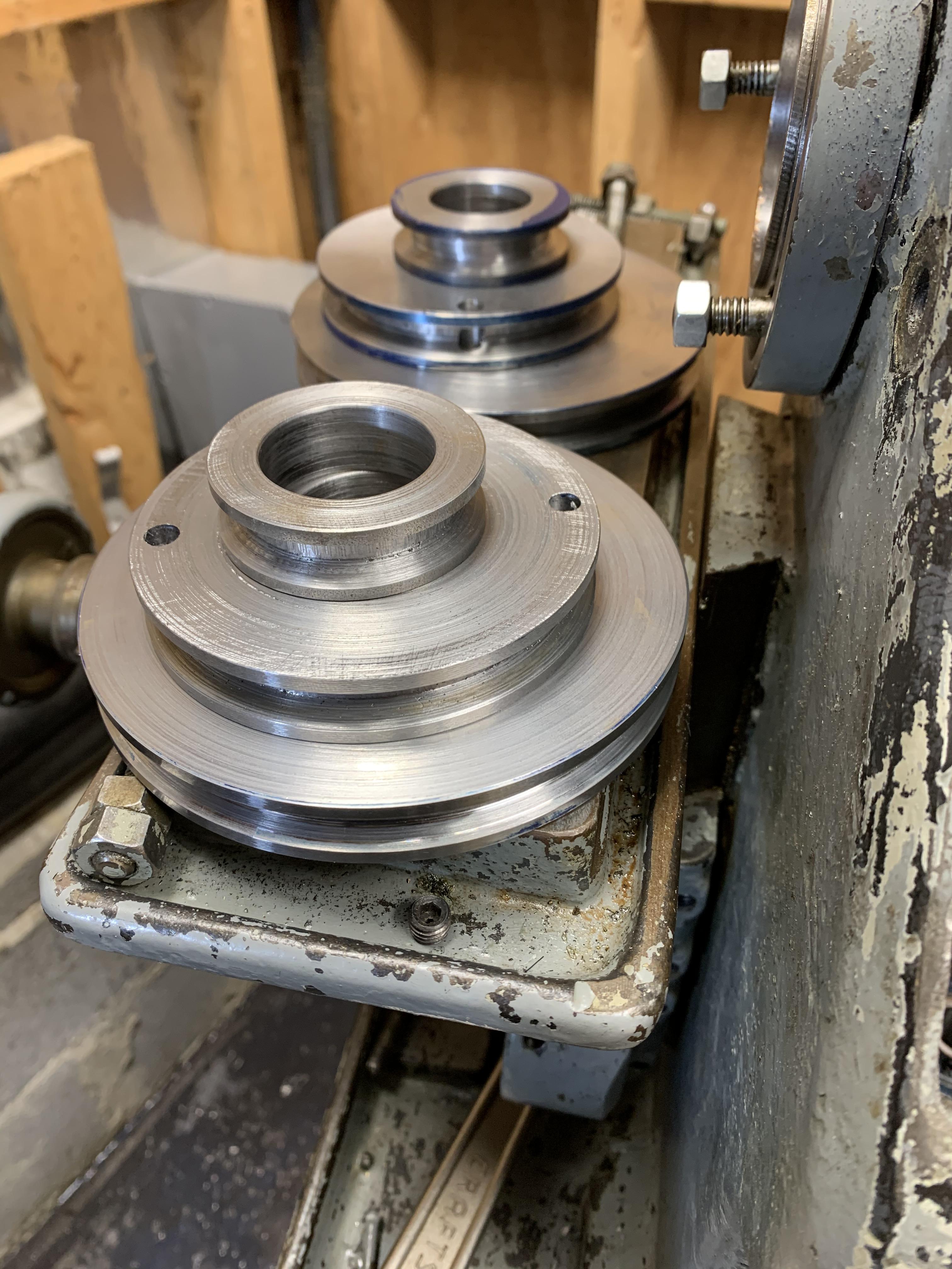
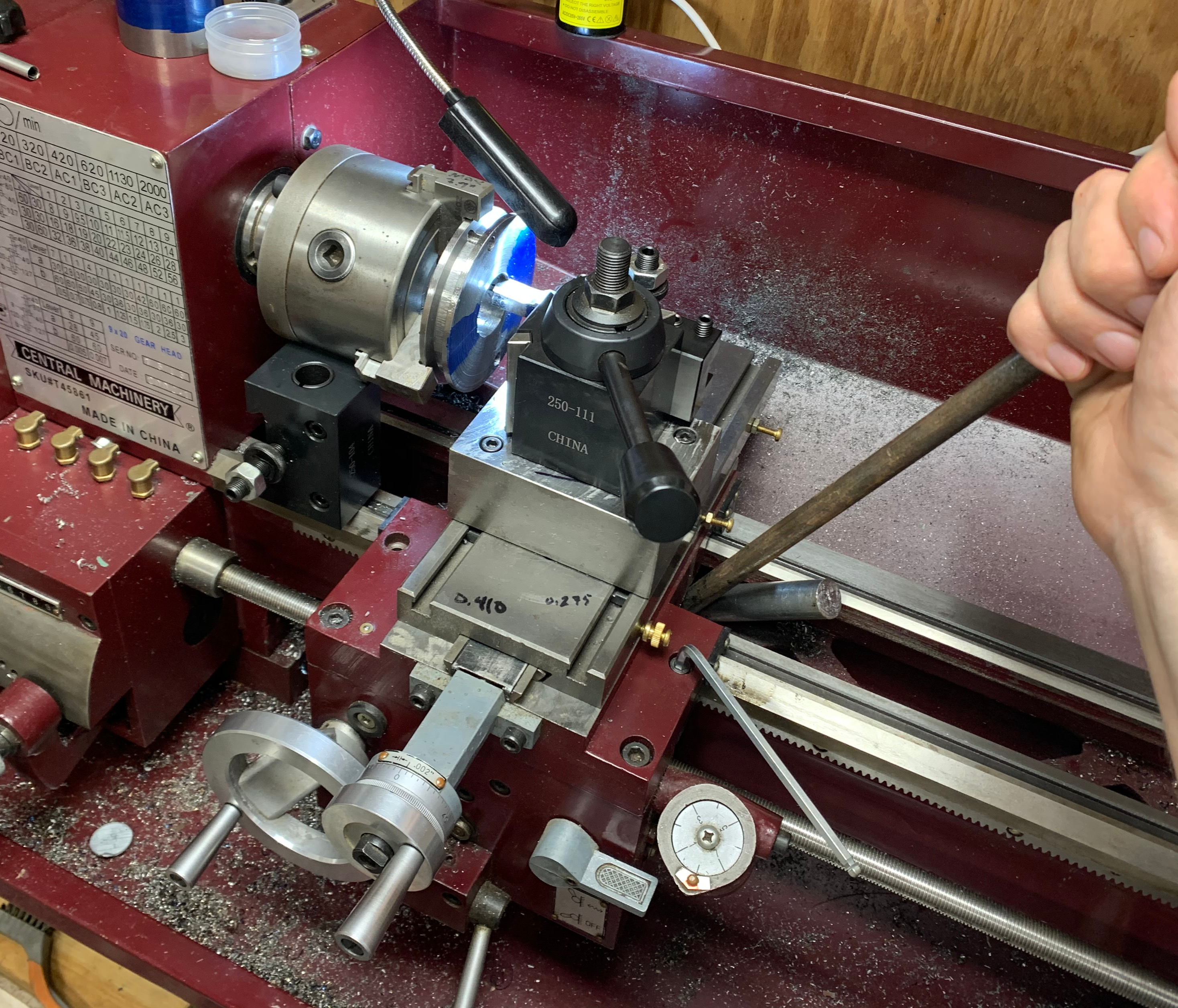
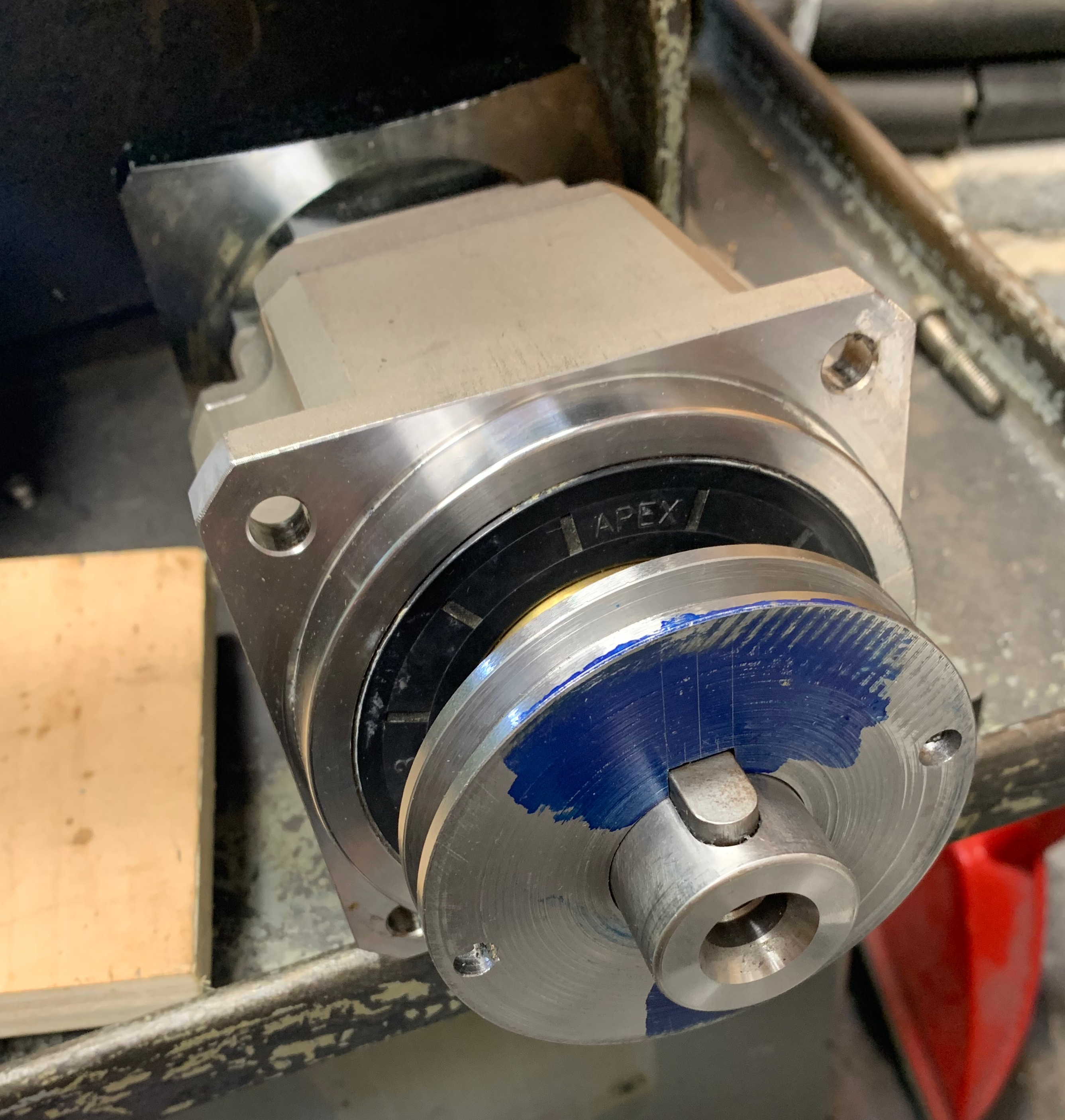
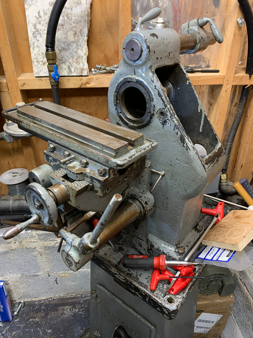
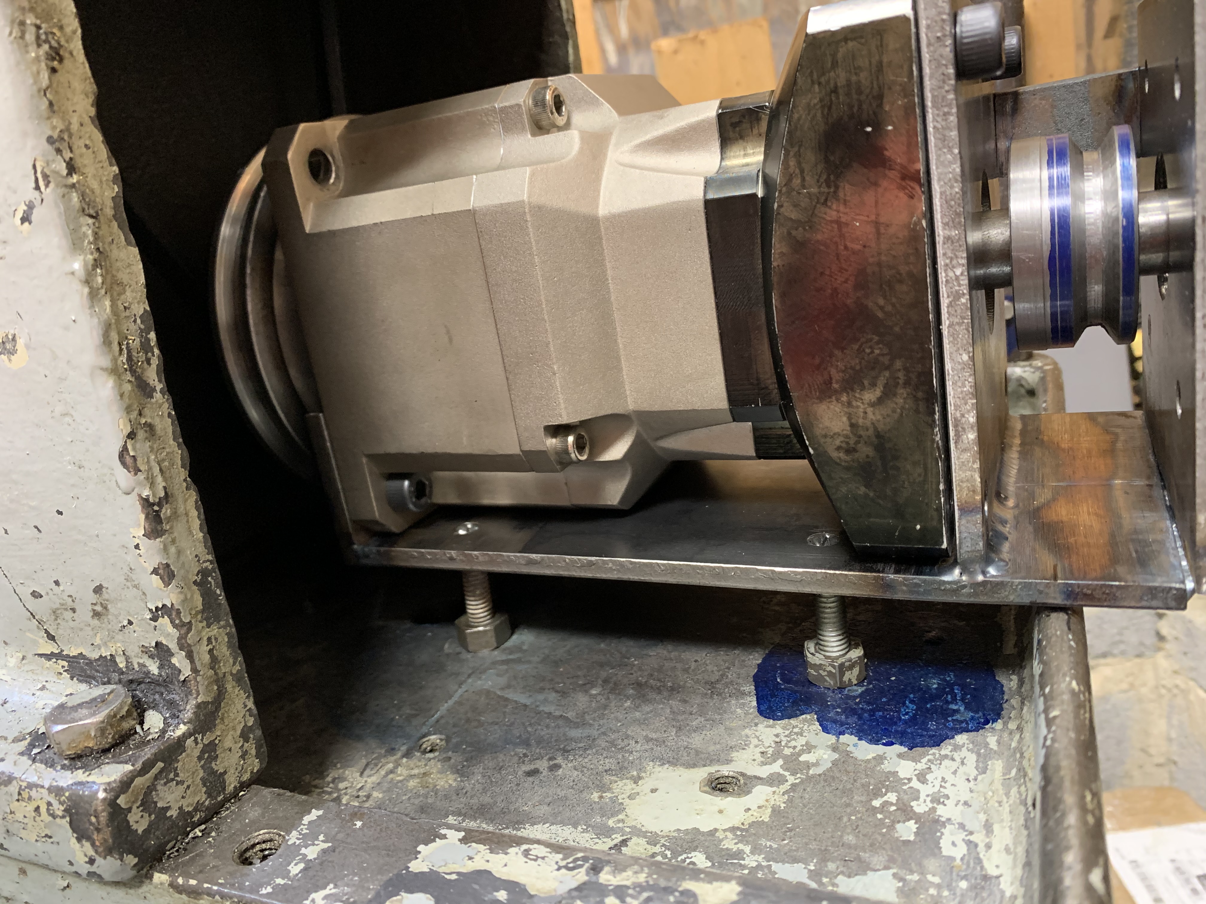
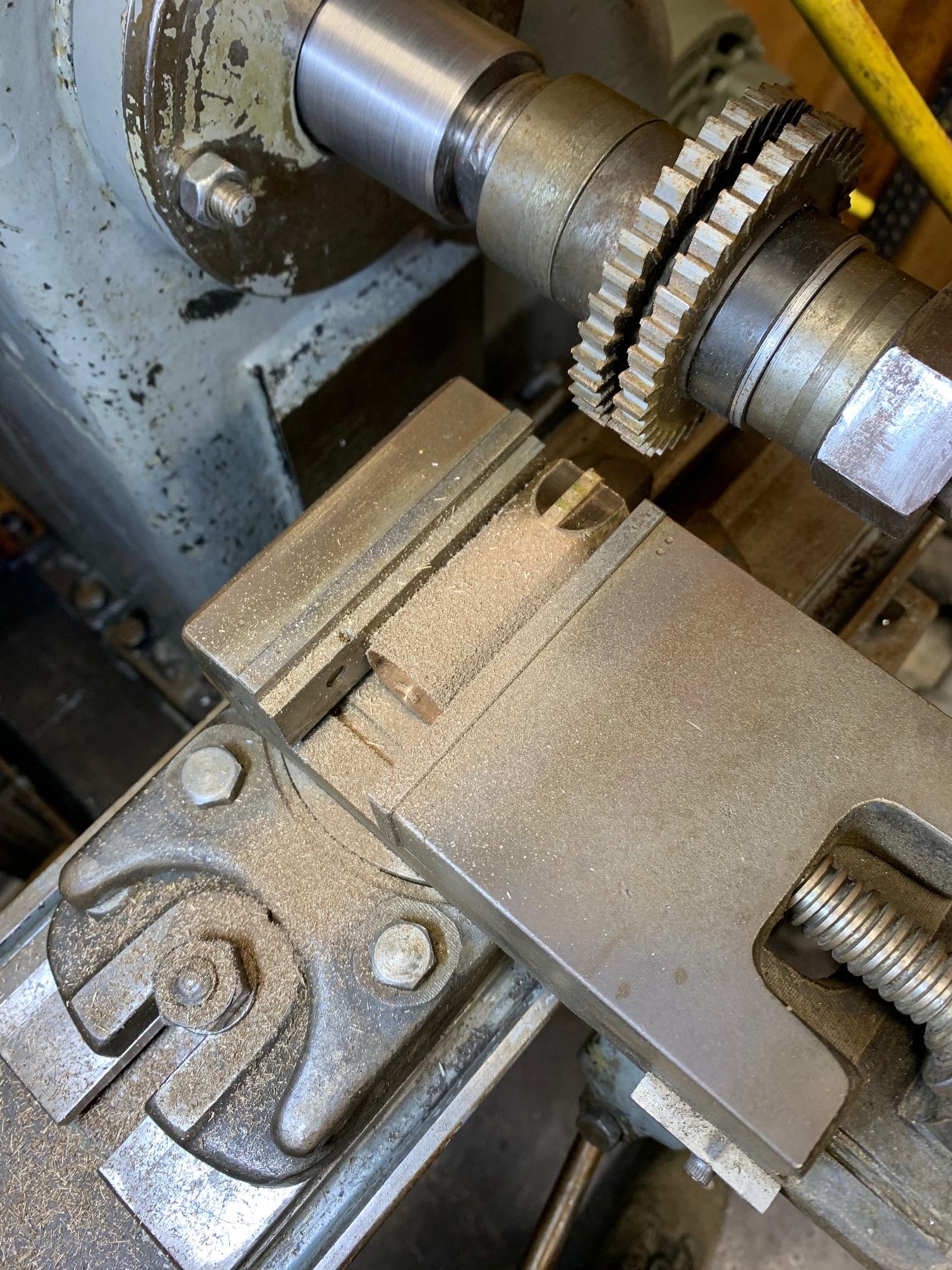
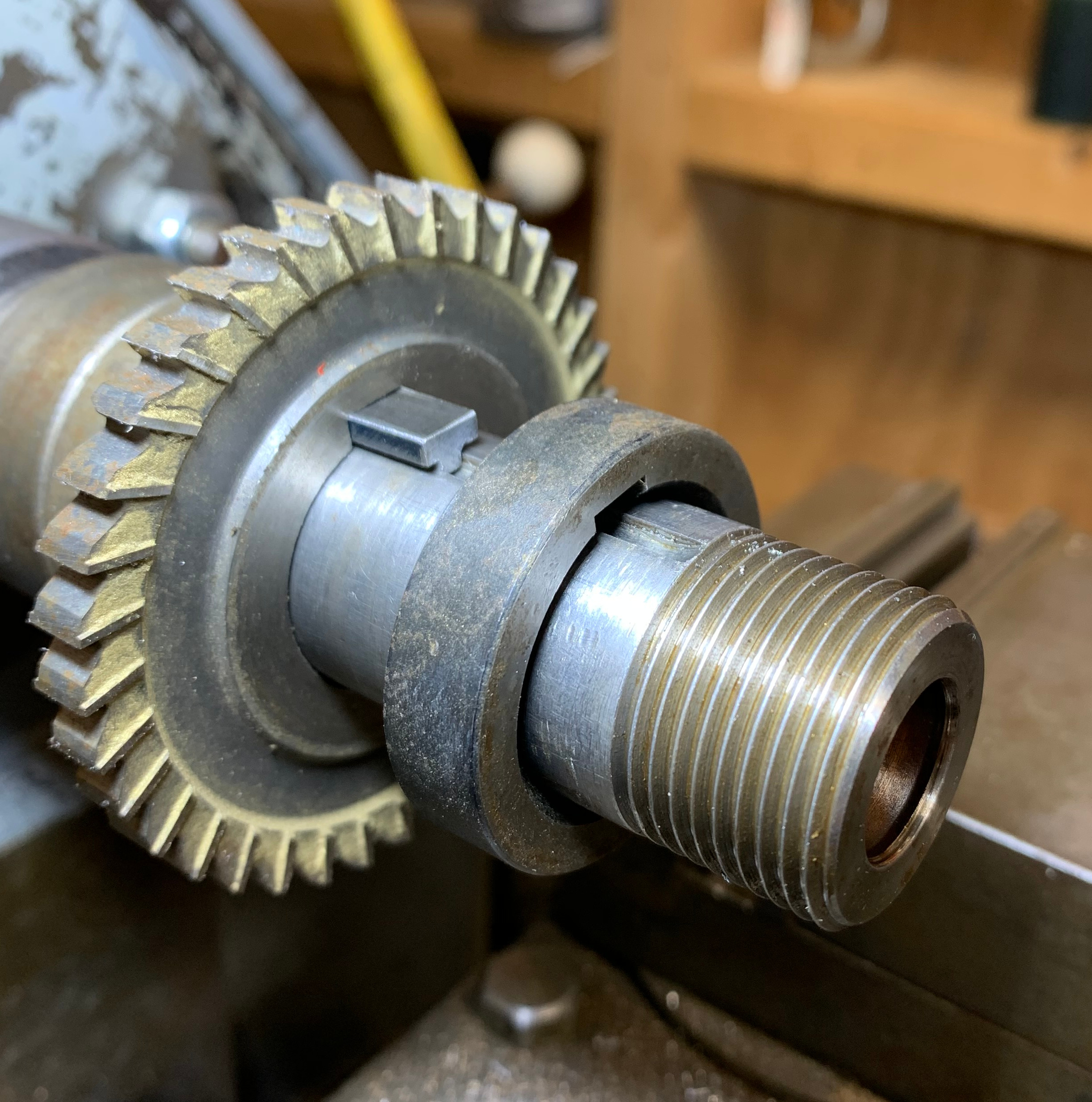
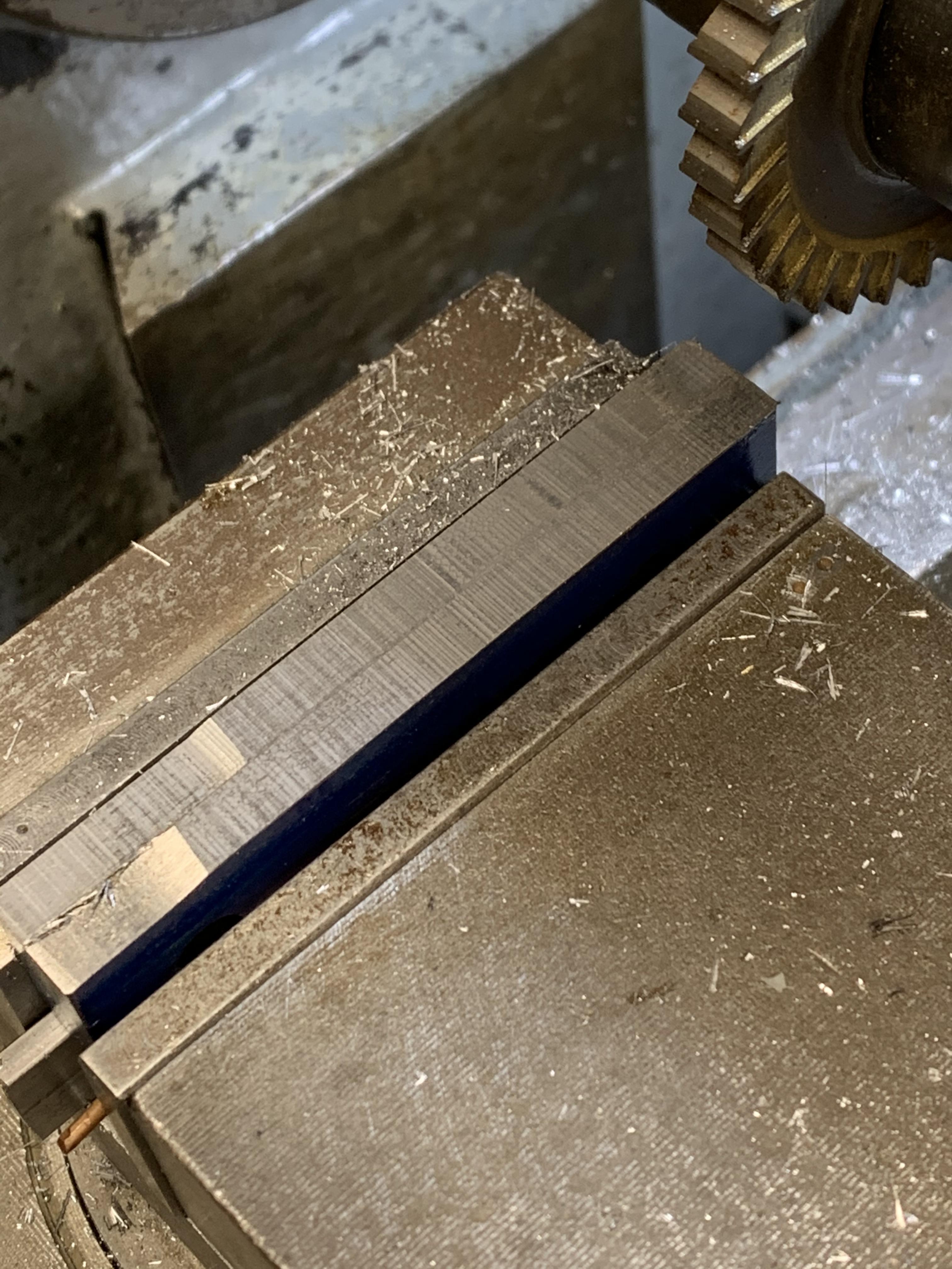
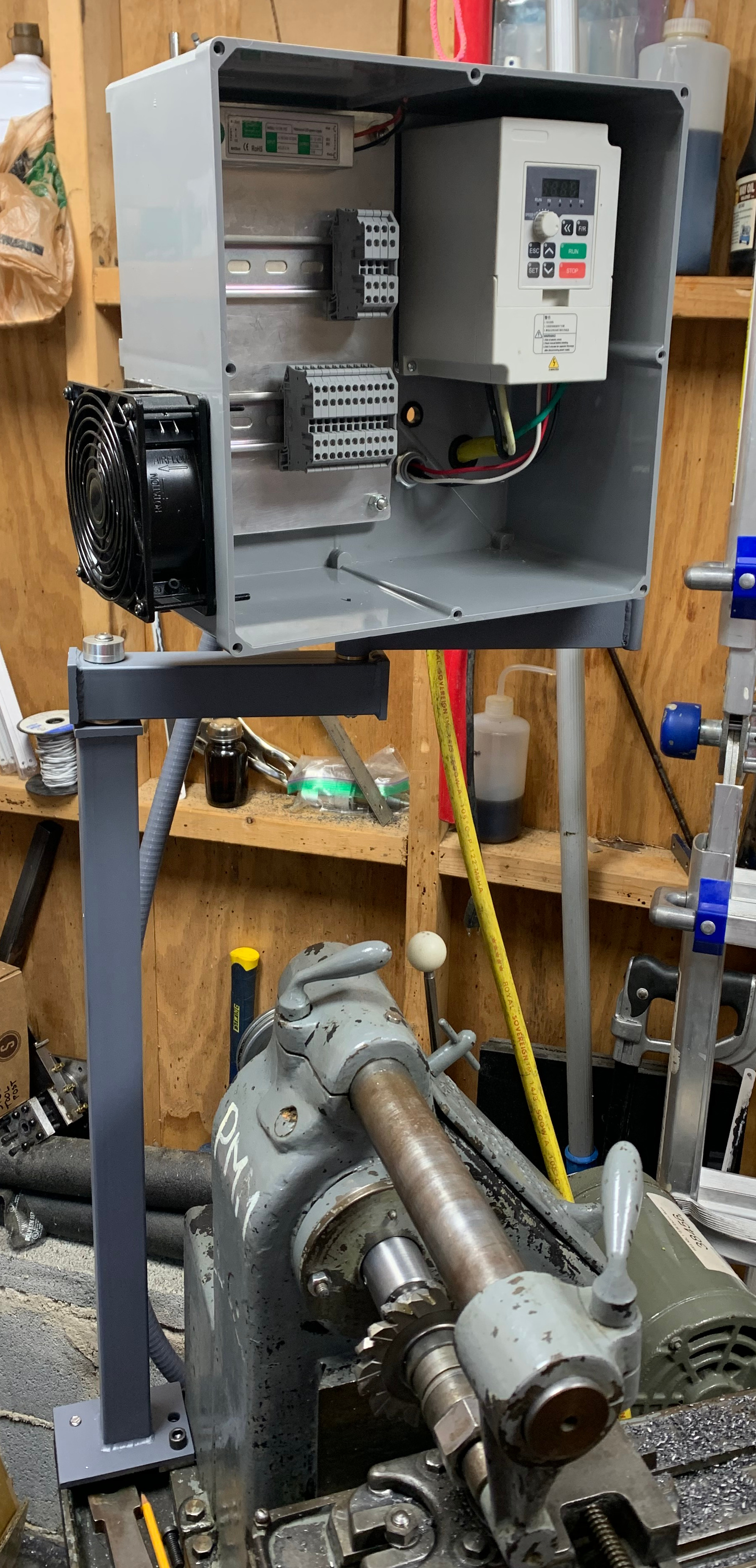
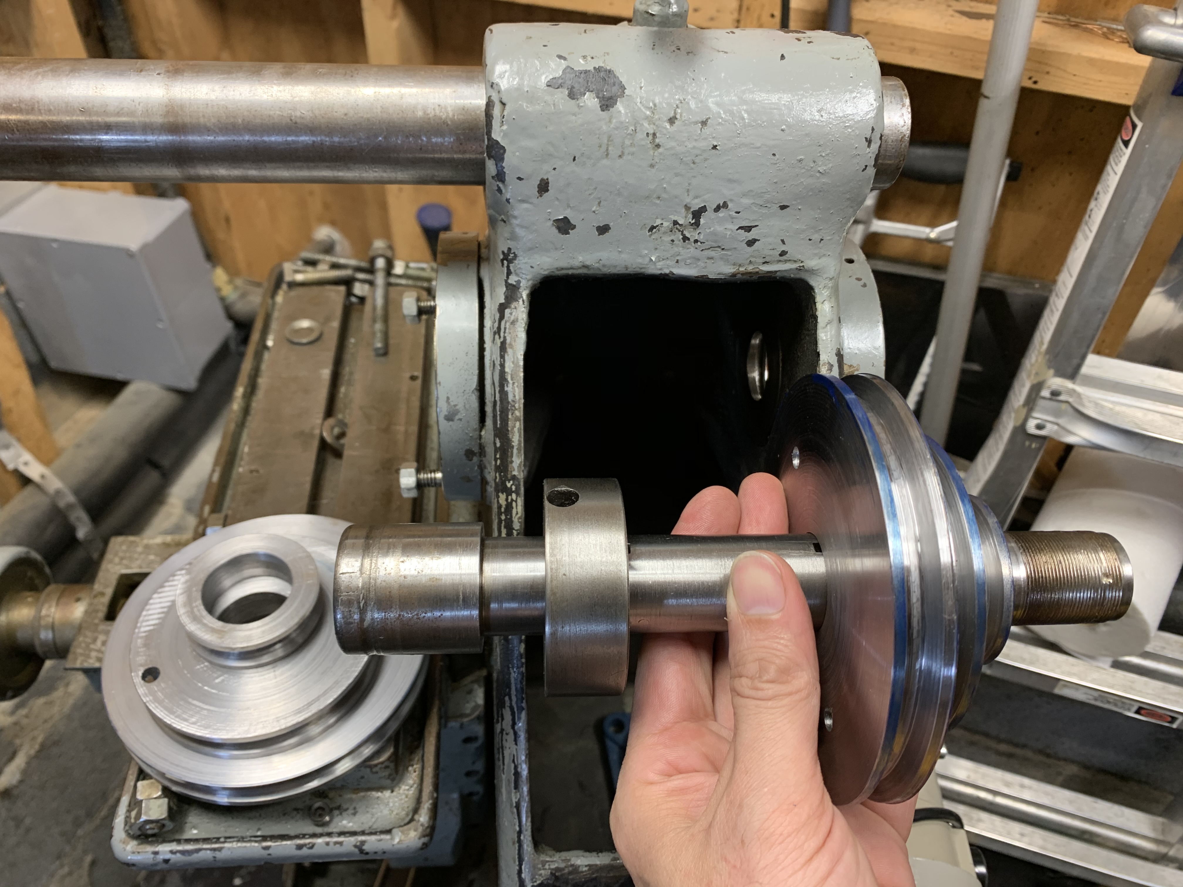
The set that go on the 15:1 planetary gearbox output shaft need a keyway. The set that go on the spindle also need a keyway but I have a trick up my sleeve. The front bearing of the spindle is covered in the back by a thick spacer . That spacer acts as a dust shield and... well, I don't know what it's so thick. But it does have a set screw and a Woodruff key, which will help me avoid cutting a keyway in the pulleys! The idea was to bolt the pulleys to the spacer. Here's the general arrangement, with the mill in the background. Everything sort-of lines up.

tKk3E1G.jpg


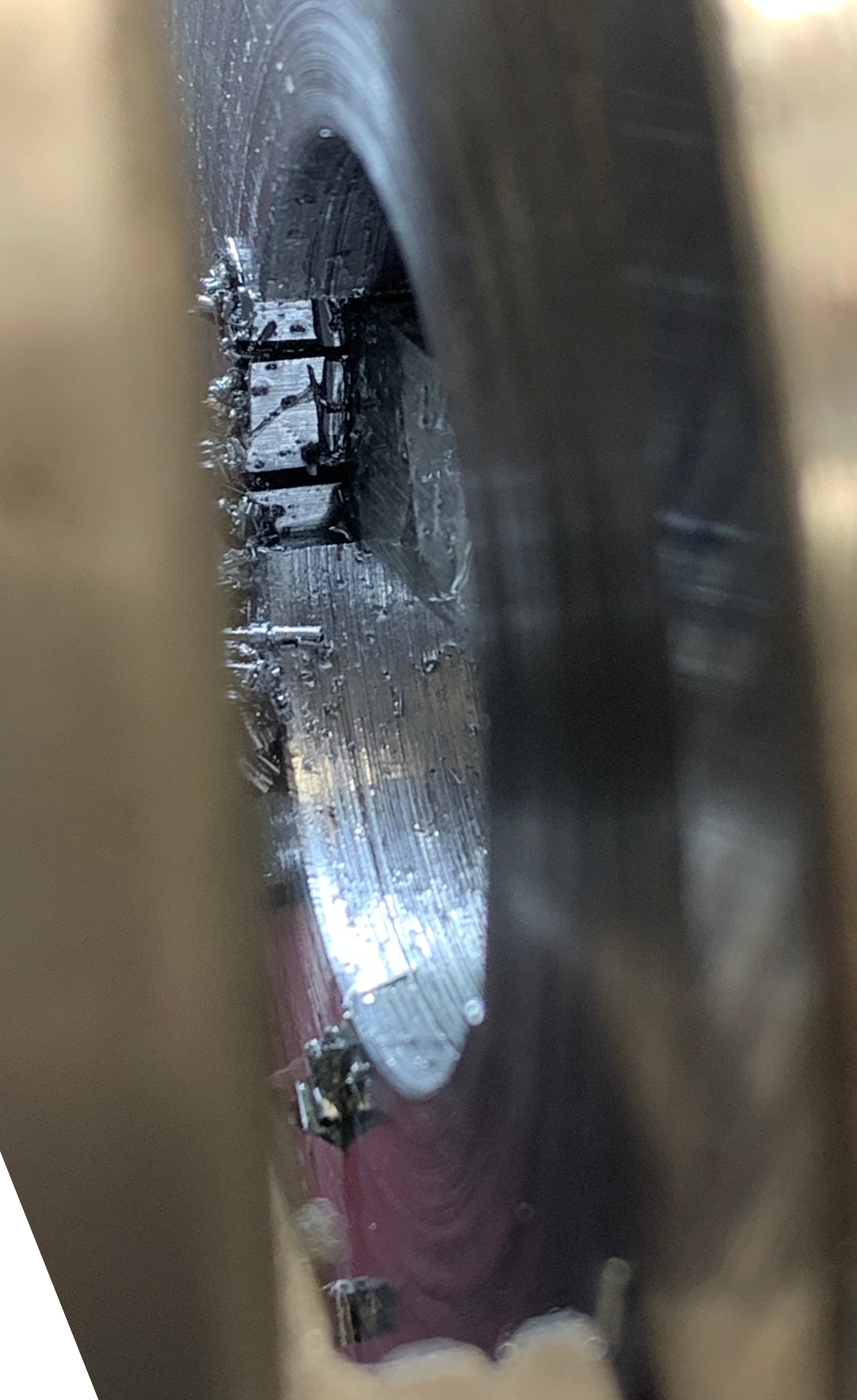
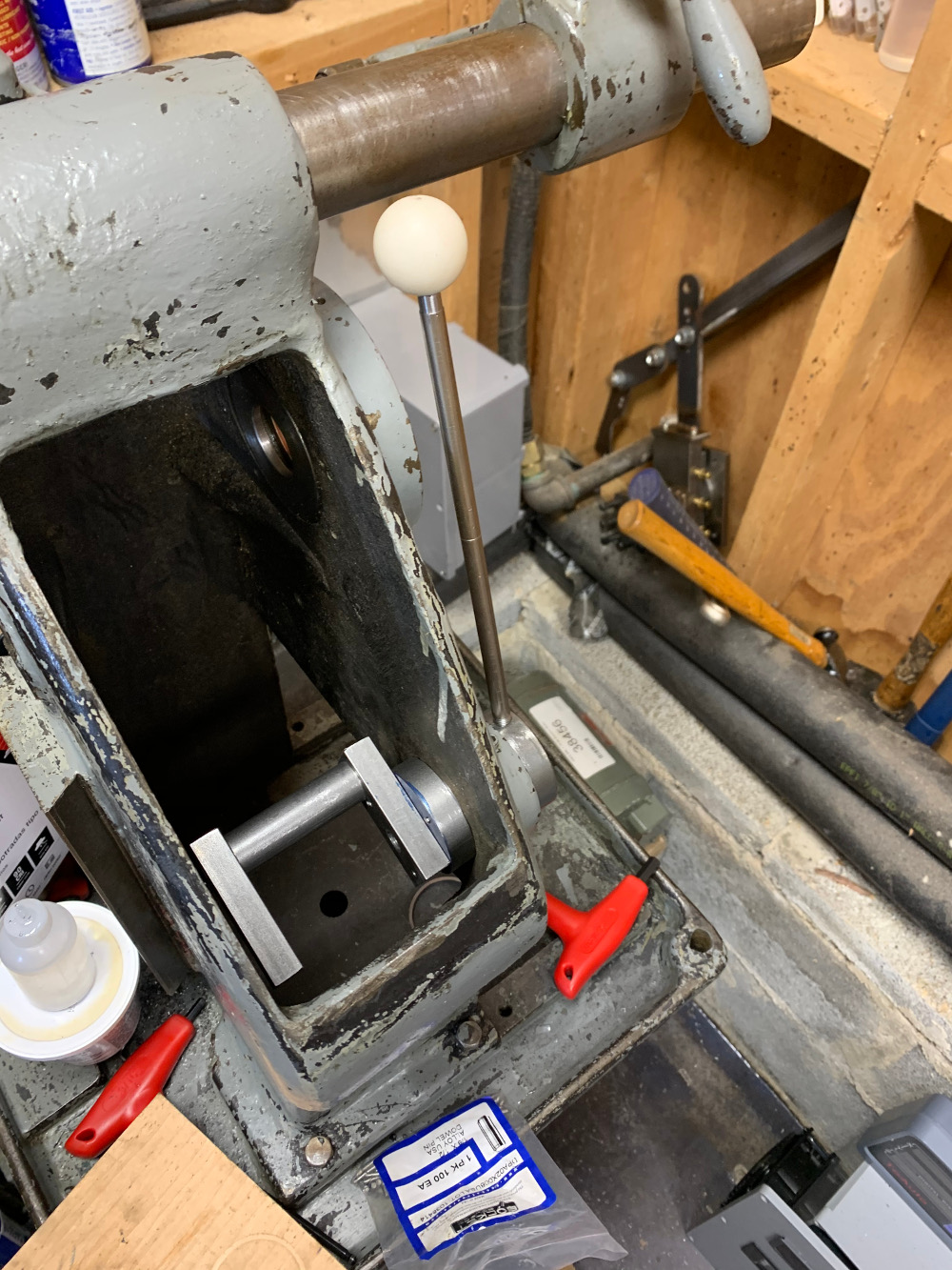
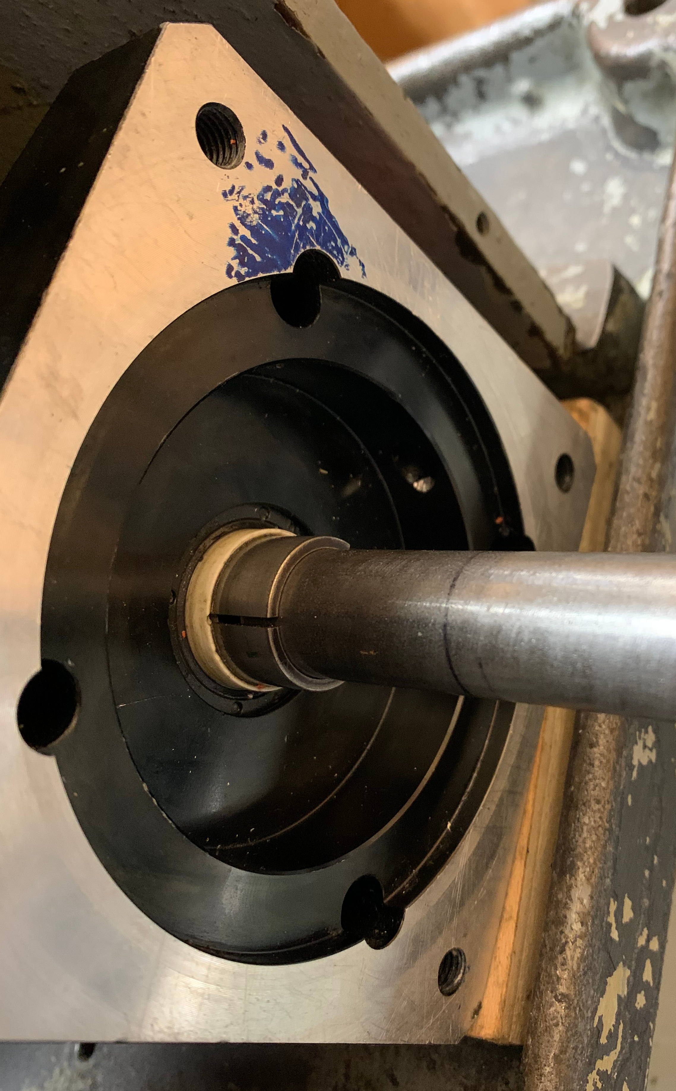
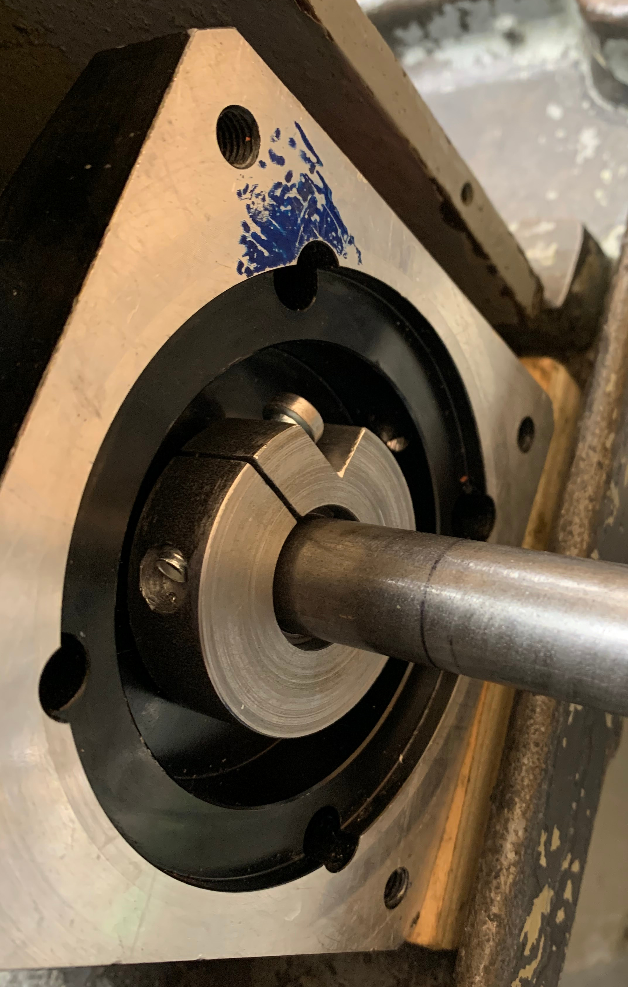
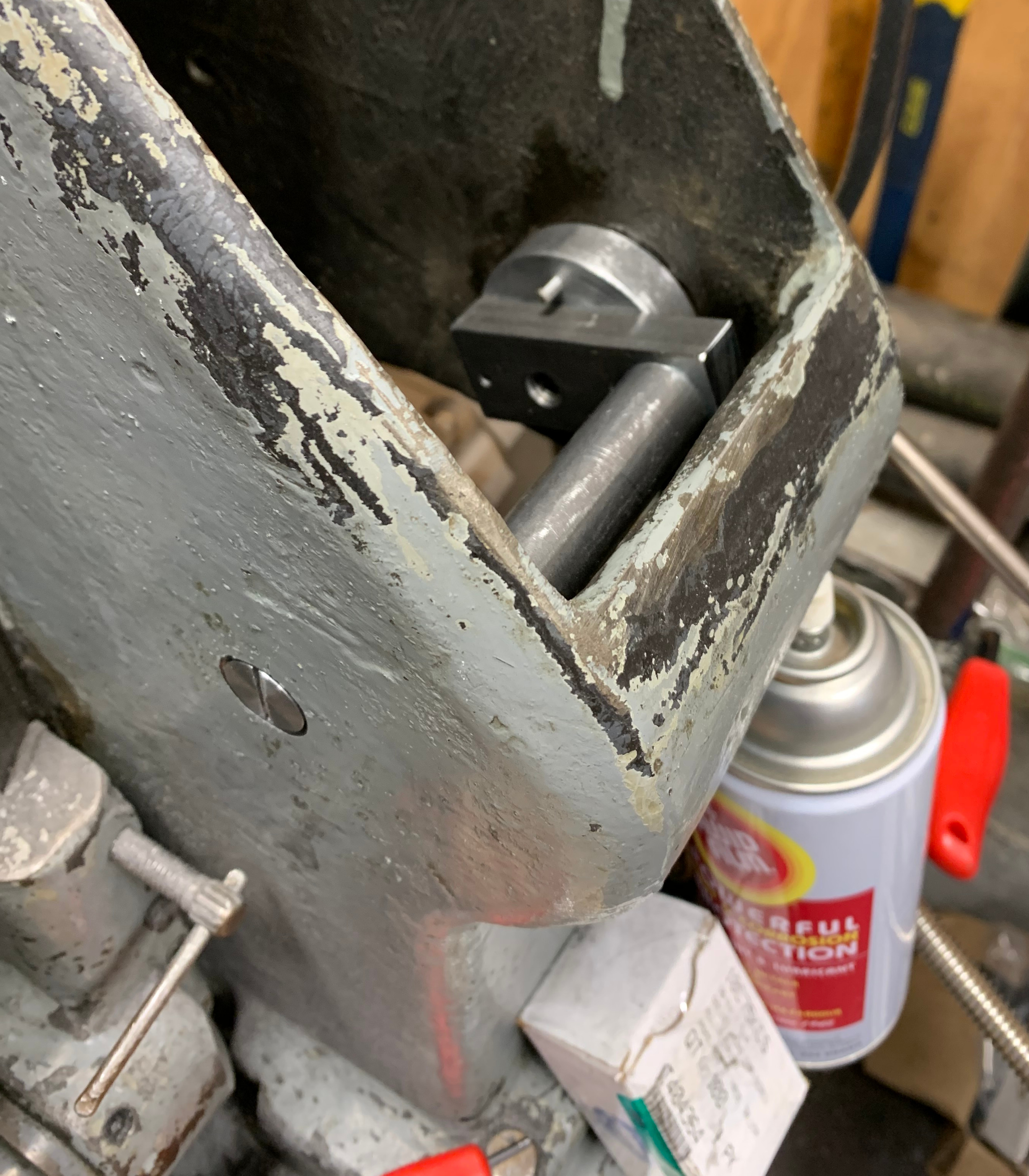
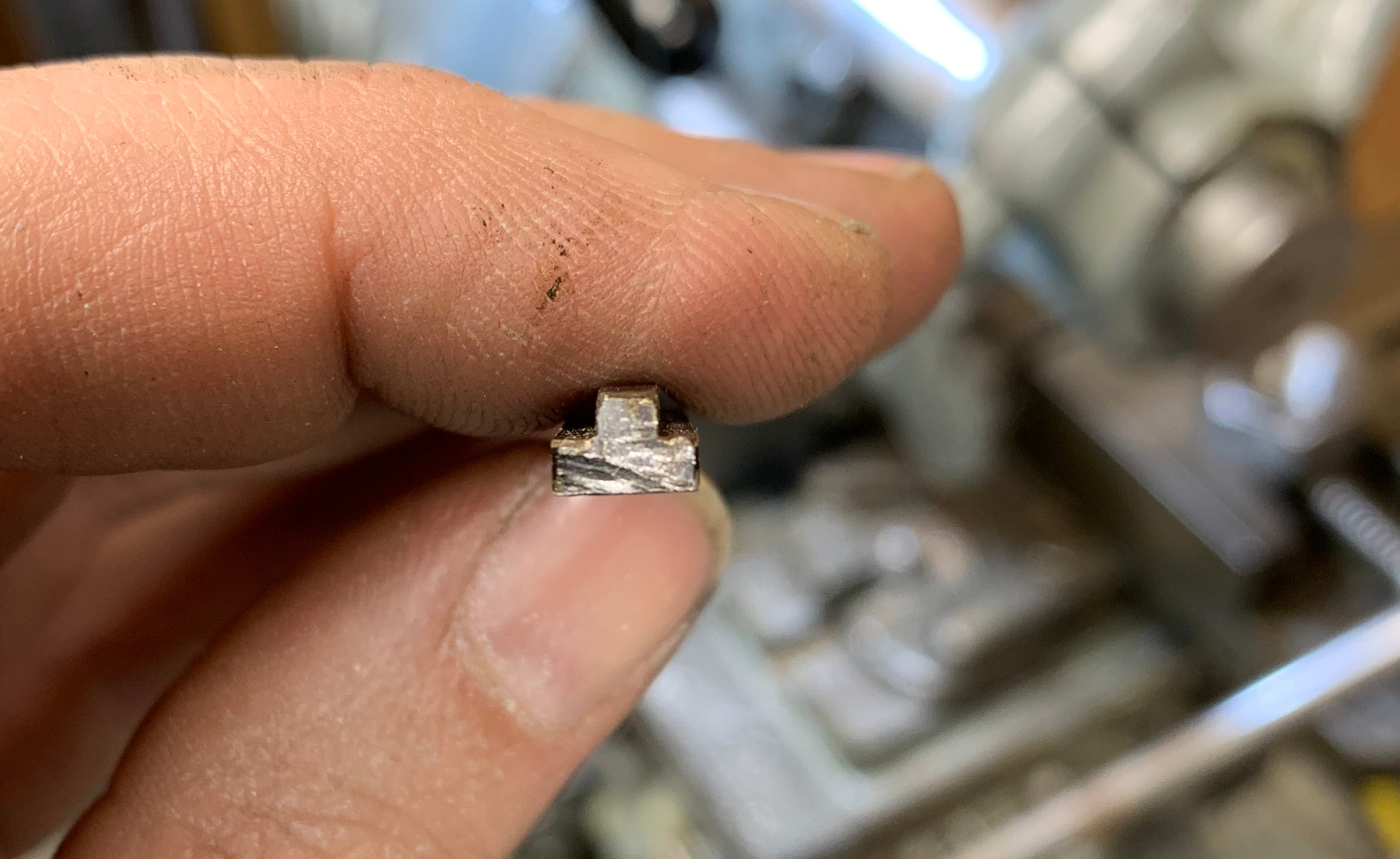
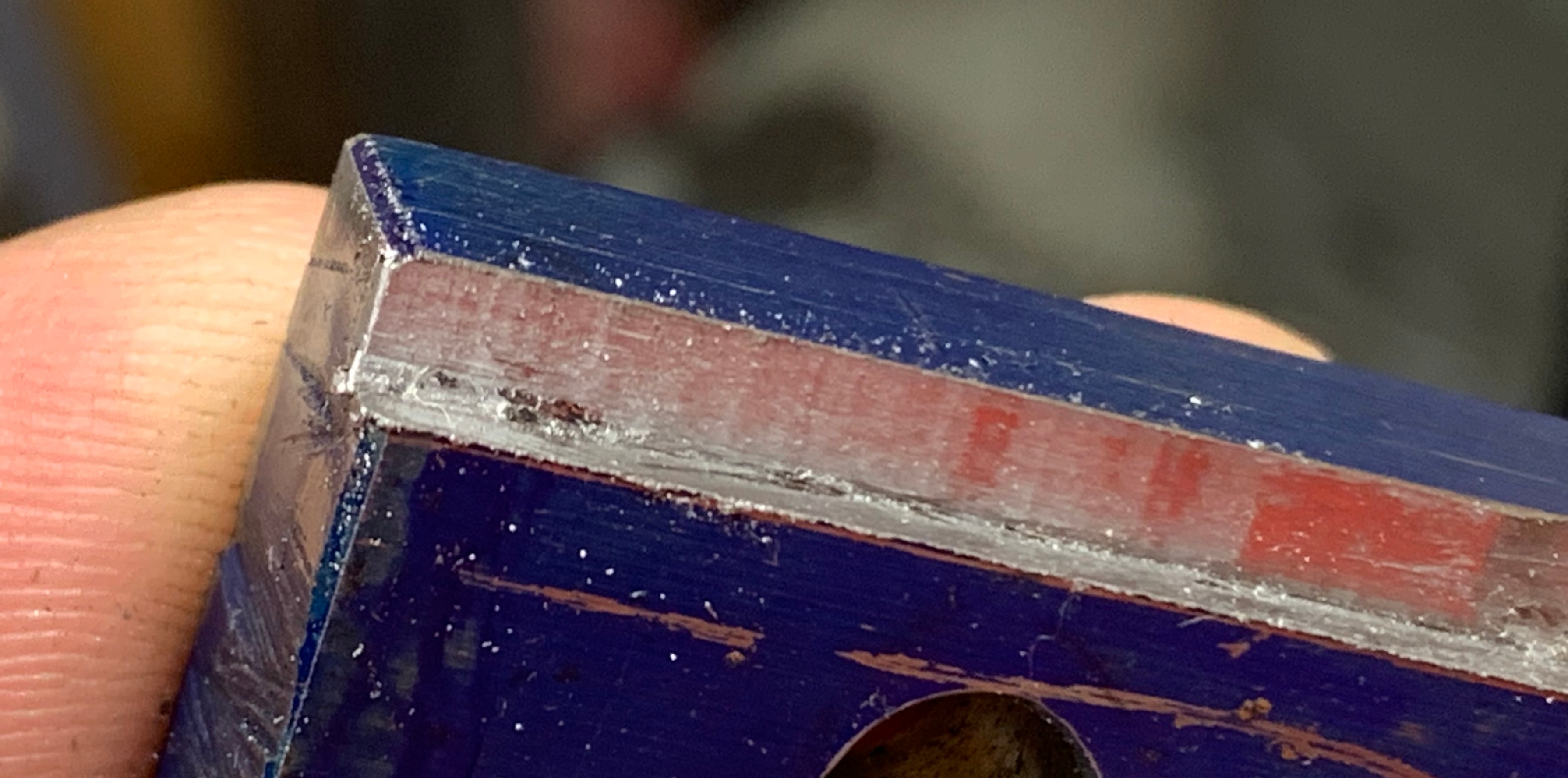
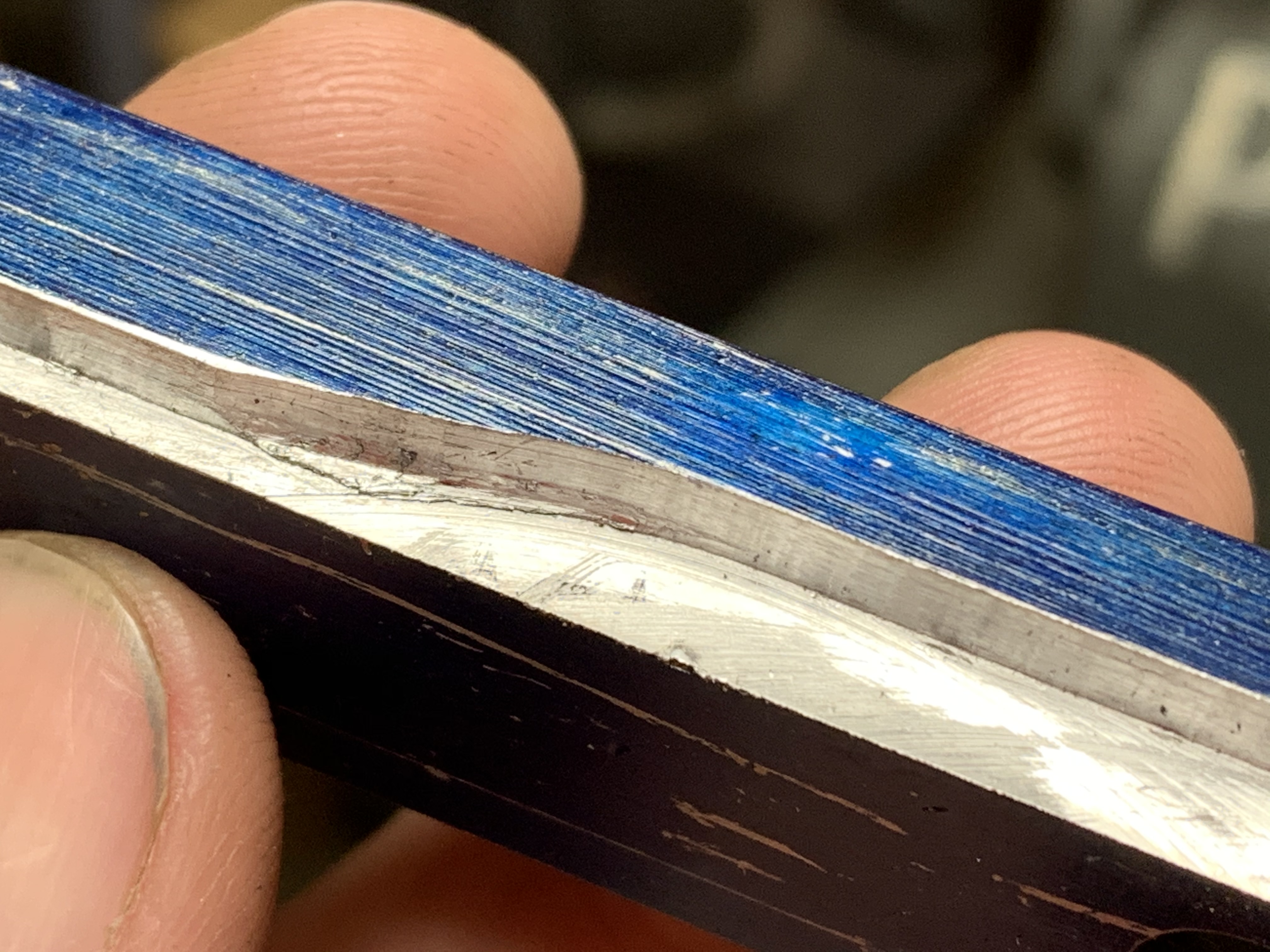
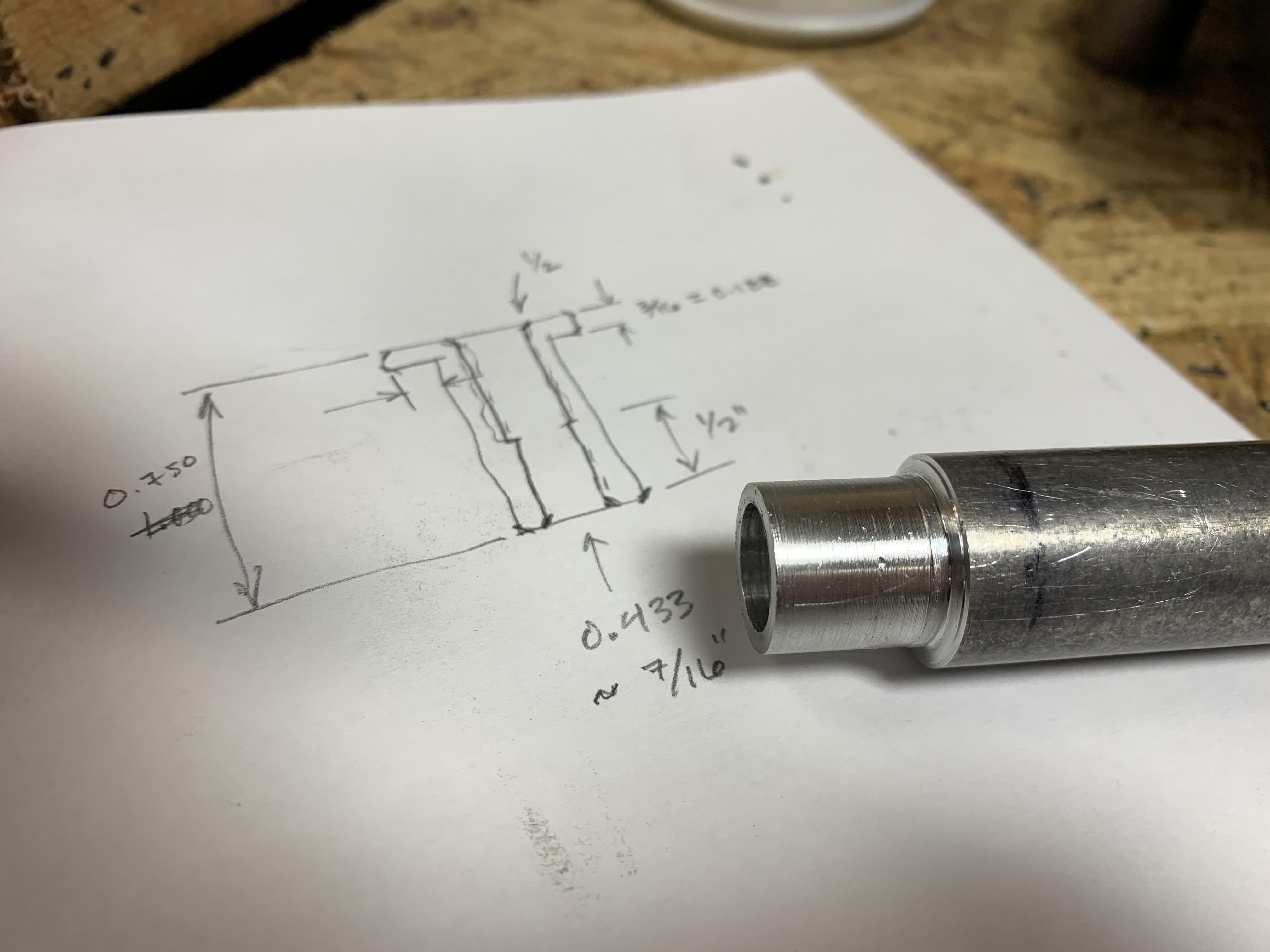
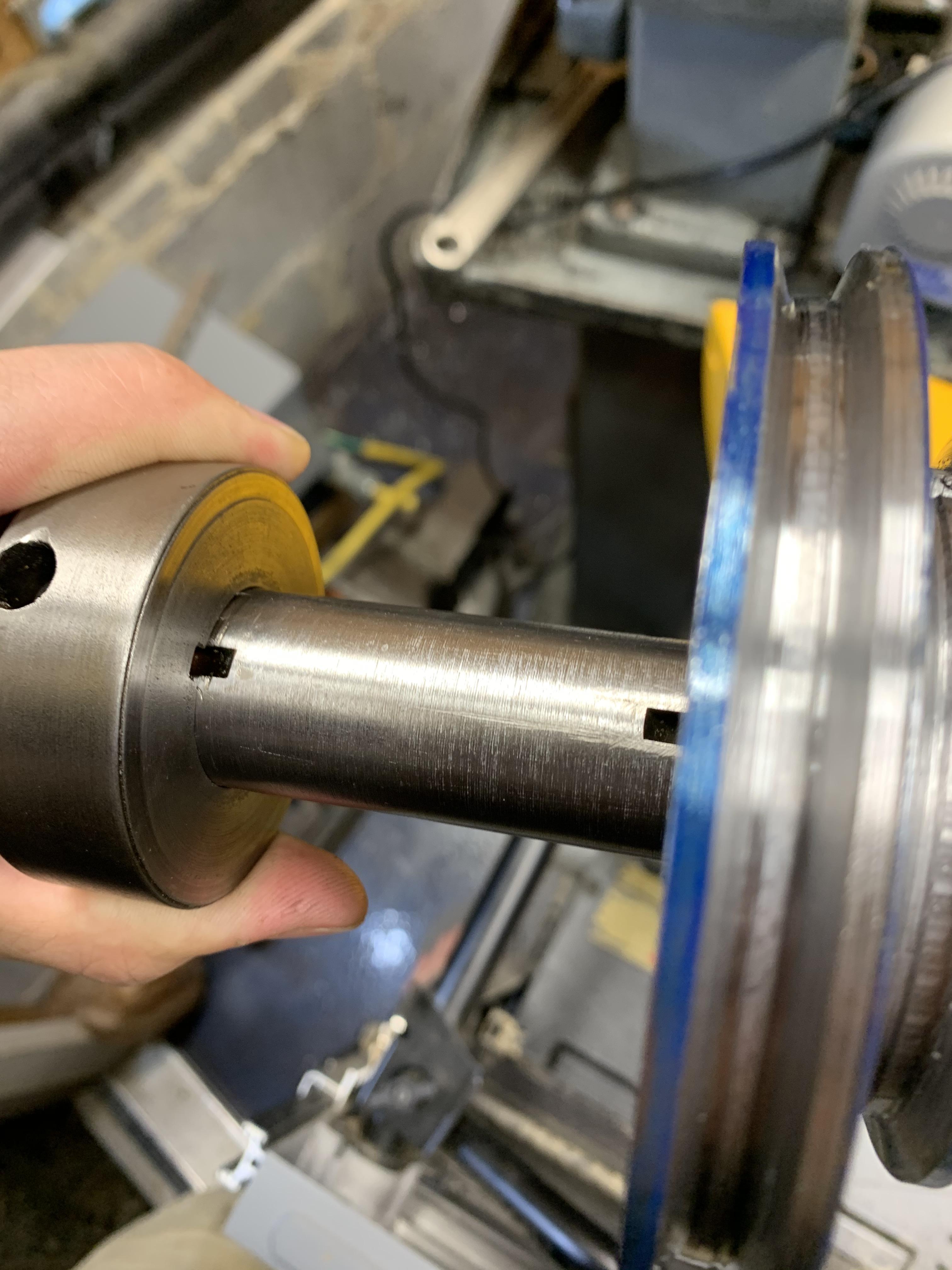
Here's the key I was talking about. But now that I'm writing it down, thinking about what others might advise, I'm not so sure this is a good idea... I'm thinking about how the pulleys could rotate relative to one another about clearance holes for machine screws. Maybe I'll still do it but make a set of shoulder screws. Or pins... 2 pins and a single machine screw. And I can choose the order of the pulleys. Probably would be best to counterbore the screws and that would be better in the large pulley. The small pulley, though, I may need to attach separately with smaller screws. Maybe countersunk flat-head machine screws. And pins. Ug, so many decisions. Or maybe I should cut a keyway and use the key at the other end of the spindle. Anyway, this is what that keyway looks like.

c4GxNJh.jpg


I won't be able to get away without cutting keyways in the pulleys that go on the transmission shaft. I found a few methods. But a broach and press. Buy a shaper. Buy a slotting attachment for the mill. But then I found this homemade lathe attachment. These mechanisms basically mount on the cross slide and have a lever to manually cut the groove.


Here's a clever one that uses the compound as a shaper ram. Again, it has a manual lever to advance the cutter.

http://madscientisthut.com/wordpres...haping-keyway-attachment-for-atlas-618-lathe/

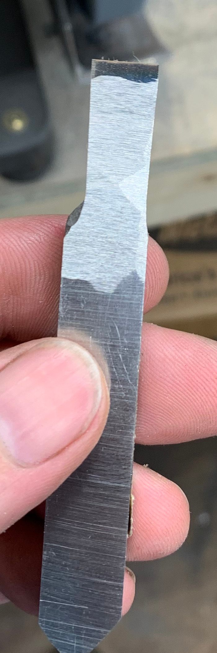
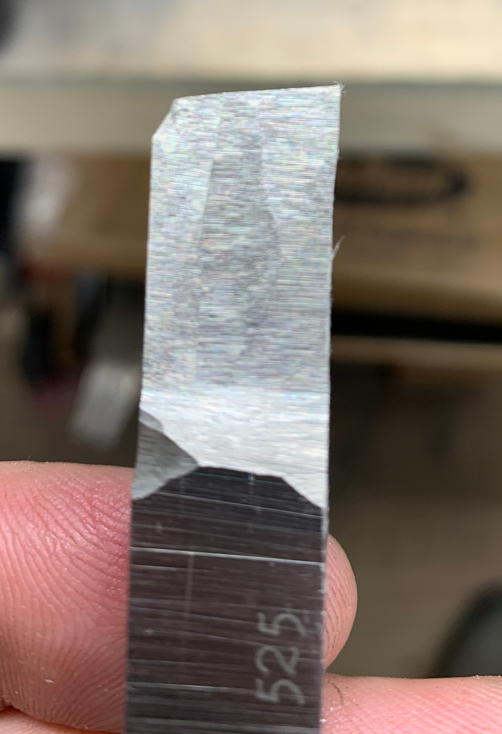
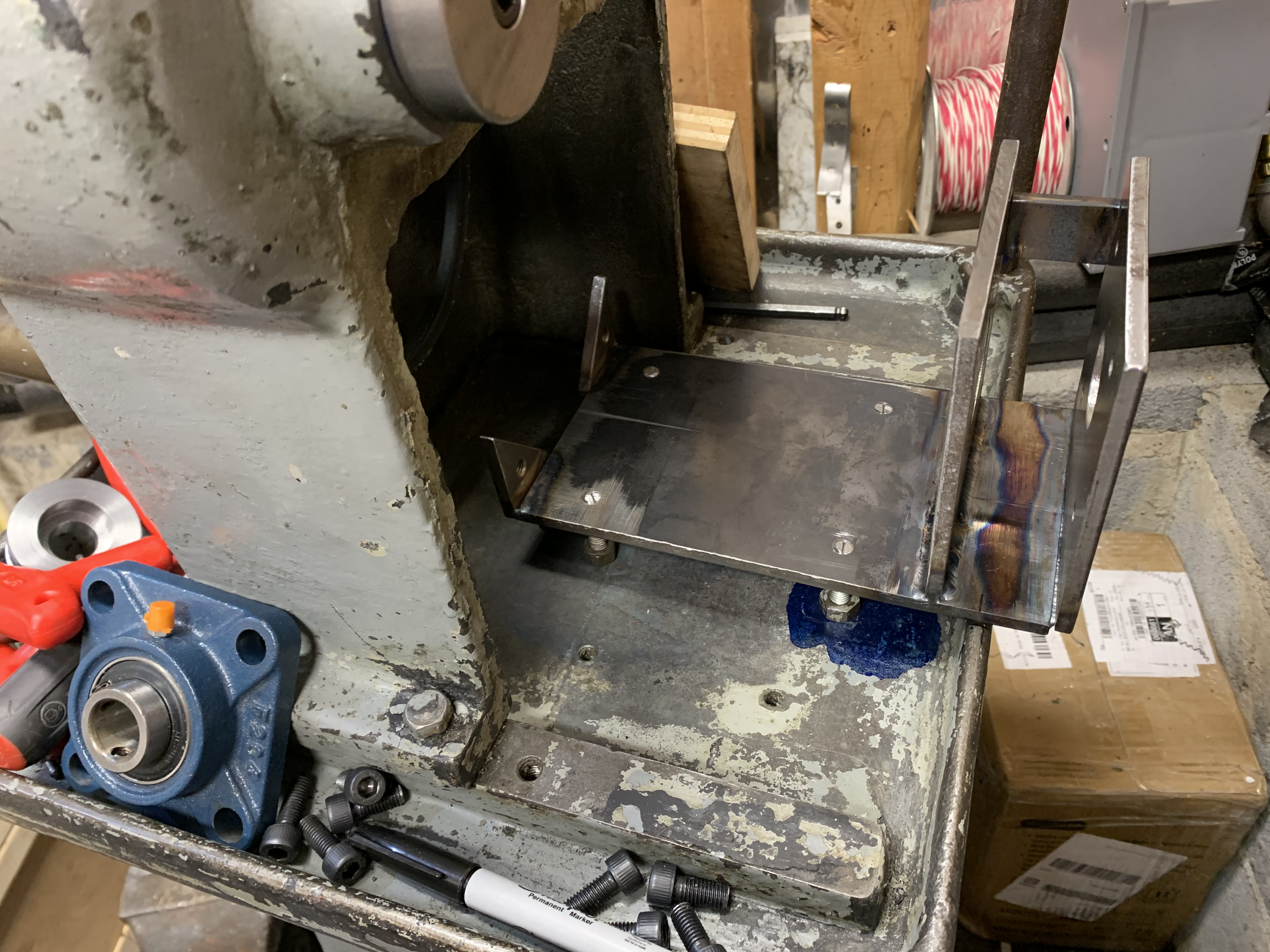
Then I thought I might just mount the cutter in a tool holder and use a lever against the cross-bracing to advance the cross-slide with enough force to cut the groove. The handwheel will spin wildly but I don't think it will be a hindrance. The trick will be to keep the overhang of the slotting tool as minimal as possible. And enough rake on the cutter that it's not trying to avoid the cut. The pulley is "low carbon steel" which I think is cold rolled. It machines OK. McMaster says it's ASTM A108 which includes re-sulfered more machinable grads but also plain sticky carbon steels. So a little rake is probably OK. And it can probably just be a HSS tool blank... Yeah, well, it sounds like good theory, right?

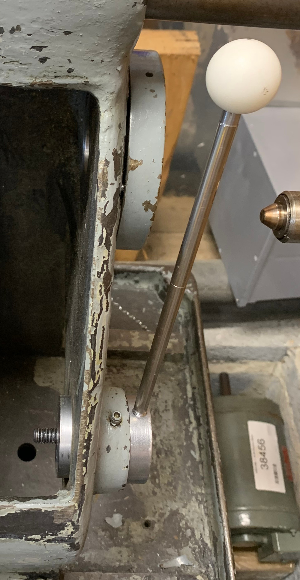
I also worked on the idler pulley. It needs to be bored and recesses cut for bearings. I think I've worked out a system for tensioning the belts with an over-center type linkage that is easily adjusted.
 
Last edited:
I decided to try cutting the keyway using my lathe.

About the cutter: I started with 4 degrees of rake, based on a post on Practical Machinist. The guy said: too little rake and the tool deflects out of the cut; too much rake and it digs in; no way to predict b/c depends on material, feed, etc but start at 4 degrees I started with a piece of 5/8 HSS tool blank, which I blued and scratched out the width of the tool. It is relieved in all directions so that only the front edge was in contact. I did leave a small flat parallel to the cut to avoid the tool digging in. Honed it was a diamond stone so it was really sharp and smooth. I made sure to sharpen the front edge and sides as square as possible, making a perfect sharp corner. I dabble in Japanese tools and the philosophy there is that the more perfect the edge, the stronger it is. And Abom says you should hone the edge of HSS tools. The width of the key was 0.4945 so I made my tool 0.4955. I had to adjust that a bit at the end but I got as close as I could with my terrible grinder.

Here's a view of the side that runs in the groove. The top edge is the main cutting edge. The flat behind the cutting edge is about 2 times too big in this photo. The relief behind the cutting edge is 0.010-0.020.

sFNTy0U.jpg


Here's the side view. This is about 4 degrees. Later I add a little more rake by tilting the tool in the holder.

Xh6NgmY.jpg


Here's my setup. It's janky but I did get it to work OK. I drilled out the bulk of the material and cut at a rate of about 0.002 per 2 strokes. There's something springy in the system so it would make a good cut and then another lighter cut. The key is about 0.170" tall so it took quite a lot of elbow grease. And every detail matters---oil, advancing the feed less where there was more material to remove, etc. In the end, I noticed some dark marks in the way oil so I decided that this isn't the way to go. Instead I'm doing the compound conversion from the previous post. Basically, take the lead screw out of your compound and add a lever. More on that next time.

So to re-power the mill, I had to make pulleys. To make the pulleys, I had to make a slotting attachment. I think the better the machinist, the farther down the rabbit hole he can go. Well, the best machinist already did a job like this and has the tool at hand.

47FKJVC.jpg


View from the back

dYDvun4.jpg


View from the front, watching a chip form.

FzaUu1P.jpg


And... success. It's a good fit.

Y1zzjLd.jpg
 
I did some more work on the tensioner. The handle might be a bit long but I'll try it as-is and make adjustments later. The handle is 5/16 shafting and there's a 1-1/8" delrin ball on the end.

vn2y5hQ.jpg


I've been piecing together the electrical for the mill. I could throw it together with some wire nuts and electrical tape but I wanted to do it right. So here's the progress so far. There's an aluminum sheet with DIN rails for terminal blocks. There's a power supply that puts out 12 VDC, and the VFD. On the front panel there's a tachometer for the spindle, a voltage-amperage meter, an hours meter, switches for the lubrication pump and lights and DRO, and the panel for the VFD. The start and e-stop are being shipped now. Once those and the terminal connectors come, I can get started wiring it up.

PTr7WyI.jpg


How to situate the box is a bit of a problem. I want it above the machine, above coolant. Not too high, just where it's needed. But the electrical box is big and it's not clear what should go where. I think I'll put the electrical box above the back right corner. The motor will stick out a bit on that side. Then I'll attach the DRO on a swinging arm so that it swings in front of the hours meter but not the e-stop or VFD panel.

I'm changing my plan from screw-actuated axes to screw and lever feed. Turns out, some of the fancier mills are set up that way. So I'll leave the z-axis (y on a mill) with screw drive. But for the x-axis I'll add an 80:1 gearbox and handwheel on the pinion. I'll need a clutch, to disengage for lever use.

And for the y-axis (the knee) I'll add a leadscrew. Eventually. For now, I'm just fixing the rack that was on it. The pinion is fine but the rack was torn off the machine. It was attached with some 10-24 socket-head cap screws, which were broken off flush. Also, there were a pair of pins which measured 0.166" or so. I ordered 0.175 drill rod, which is +/- 5 tenths. I also ordered 0.1755 and 0.1760 reamers. In my limited experience, a hole reamed to 5 tenths over the pin diameter gives a nice fit. I'll drill out the pin holes in the rack on the drill press, bolt it into place, and use it as a drill guide for the hole in the mill. Then I'll ream the holes in place.
 
Finished the tensioning mechanism. The casting is a bit rough but close enough. The magic is in the offset shaft. The offset is set using those 1/2" bars. There's not a lot of room so I had to use some tricks. Too much to explain, probably. Anyway, the last steps are to add a stop to get the over-center effect and brace the other end of the shaft, and finish the idler pulley. Then I can run the mill. And I'll probably make T-nuts for my first project. It's like the hello-world ritual of computer programmers or the champaign bottle of shipwrights.

sAbm9Jo.jpg


The screws and pins came for the vertical rack. Worked like a charm. I re-assembled the knee and got the table back on it. The motion is smooth. Now I need to order gearboxes, if I've made my mind up.

nF6oaeM.jpg
 
Had some more progress with the spindle drive. I got all of the pulleys fixed on the appropriate shafts. By hook or by crook. I'm trying not to weld my way out of problems but I did stack the pulleys and weld them together---just a tack, actually. I may eventually need to disassemble and weld more but until they break, I'll leave it. It was touch-and-go. I stacked the pulleys on the shaft, then made some tiny tacks (TIG, of course). The first tack was just too much weld metal and it tipped the pulley enough to pinch the shaft. Then I made a tack on the opposite side, hoping that the shrinkage would fix the problem. It didn't help but I clamped the stack of pulleys during future welds, which prevented the warpage. So the stack of pulleys on the transmission is sort-of permanently on the shaft but the other cluster slides on and off the shaft.

fMilbM4.jpg


Still need to work out the drive side of the transmission. I had originally designed the drive for a 3450 RPM but changed to a 3-phase 1750-RPM motor. I think I will step the motor speed 2x at the input to the transmission. Would be fine either way but this is the speed I designed around. So... 2 more custom pulleys. I want to buy but it's just not easily available. A 2" pulley for 3L belts with a 3/4" shaft? Can't find it anywhere. If I had known, I would have designed around A belts (4L) for which there are many more options. And for the motor, which has a 5/8 keyed shaft with a 3/16 key---no, McMaster only has it with a set screw.

I fabricated a mount for the transmission. It was a chore to get it mounted on the base. I drilled the mount tap size (1/4-20) then tried to use a centering punch to mark the location. Turns out, the cast iron, with it's chilly hard exterior, can't be easily marked with cheap punches from the usual suspects. So i used a hand-held drill with the tap bit to mark the center of the first hole. Then I drilled it with the clearance bit. After installing a stud with appropriate jam nuts, I worked on the next hole. All the while, the main casting of the mill is in the way. And there's nothing to make you feel foolish like using a hand drill while you stand next to a drill press.

9wpQbrX.jpg

FWV48KB.jpg


The input of the transmission is sort of a collet type arrangement. Took a while to figure out how to secure an input shaft. You're meant to put a collar over the collet. There's even a hole for tightening the collar's screw. (The collar is backwards at the moment so you can't tighten it properly.)

sXxWdXF.jpg

s0xQmPw.jpg


The tensioner pivot is finally installed. It's close but not perfectly coaxial, despite making a tool to mark the center. There are many places where I could have gone wrong. But it's close enough to work---feels a bit sticky in one spot. The final item for the tensioner is the locking mechanism. The over-center idea just isn't going to work out. Instead, I want to hijack the setscrew hole and use some kind of spring-loaded plunger to index the position of the tensioner.

The idler was originally designed with ball bearings and no provisions for positioning them on the shaft. Not sure what I was thinking. But the bearings were quite large and it made the pulley too wide. So I switched to roller bearings and a set of thrust bearings on either side. It's silly but appears to work.

GFCimad.jpg


I finally got everything sort-of working. I wired up the VFD and read through the 150 parameters to figure out which I needed to change. Turns out, there were only a few that I couldn't use as-is. Here's a picture of the mill cutting into a bronze bar. Turning that direction loosened the nut so I had to re-arrange, flip the cutter over, and mill from the other direction.

lwcwOhf.jpg


At that time, I didn't have a key for the cutter so it was very light cuts for the first parts. I managed to make a hybrid 0.050-0.250 key.

lk2itll.jpg

zeBroi8.jpg

z9Y4ptA.jpg


Then I started making T nuts---because that's what you do. It's the equivalent of a "Hello, World" program for a horizontal mill. I started with a chunk of mystery metal and it ended badly. I noticed a lot of noise at the end of the first cut but carried on. In the second cut, I could feel the cutting become difficult. When I stopped to figure out what was going on, I noticed that the edge of the cutter was completely chowdered.

Here's some stock preparation. Looks bad but it's fairly smooth. The gibs need tightening, looks like the arbor is wobbling a bit, and the operator needs experience! Also, I won't be able to manage with this lever feed.

M7XpB6M.jpg


Now, cutting a shoulder, I hit some hard spots. Checked with a file, too.

olzCVcf.jpg

olrxEvY.jpg


And here's what it did to the cutter

gzxjliE.jpg
 
Then I started making T nuts---because that's what you do. It's the equivalent of a "Hello, World" program for a horizontal mill.

Great line!
I like the way you think.
-brino
 
Well, I finally got back to the mill last night. Honestly, I thought this project would take less effort and that the results would be better. In the back of my mind, I doubt that this will work out in the end, so I haven't been working on it for a few months.

Last night I managed 2 good cuts. Turns out that the gibs weren't tight enough in the Y axis so when the cutter bit into the work, the X axis (traverses parallel to the cutter) would rock. Belts were slipping, too. So I tightened up the belt, locked the Y axis, and centered the vise over the knee. The rocking is no longer visible. Now it is apparent that lever feed is not going to work at all. There is so much lash in my arm and the gears that I can't bring the work to bear solidly on the cutter. I've heard people say good things about lever feed but was it roughing cuts in steel? If you have used a lever-feed machine, please tell me about it.

If I can get 2 good T nuts made for the vise and machine down a brass nut for a 1/2-10 lead screw, I'll be a long way toward a power feed on X.

When I look back on the time and money, I might have been better off spending it on something I could convert to CNC. Time is the only thing they're not making more of and I want to make better use of mine. The clucking of the gray-bearded machinists might be right---not everything is better with a computer. But still... Well, I'm far enough in that I need to finish the project, so I will.
 
I am sorry this has not been going well.

Restoring an old machine is often a marathon of chasing one issue after another.

It sounds like you are making progress, albeit slower than you want and hard-won.

I still believe it will be a useful machine when you are done.

-brino
 
After considering my situation and the weight and money involved, I decided I'd better finish the project. Anyway, the problems I was having before are mainly due to an ad hock belt tensioner and lever feed. Oh, and the paper towel I was using to protect the motor wasn't good for moral, either. But all these problems can be solved.

Got some of the electrical details worked out. The electrical box is mounted securely on an arm. The DRO mounts on another arm but it's not installed yet. I'm using Pheonix UT series terminal blocks to make the connections. In an industrial application they use wire channels, too. The machinist clamp and silly tape arrangement is critical because there's no hinge.

7gF90mR.jpg


There's an hours meter, spindle power consumption meter, the front panel for the motor controller, E-stop, and a start button. I'm going to replace the start button with a selector type switch for Forward/Reverse. Also need an On/Off selector switch. I'm surprised at the difficulty in getting this wired up. I'm an electrical engineer so I thought this would be fairly straightforward. But the documentation for the V70 VFD (from stepperonline.com) isn't great, which results in several additional Digikey orders and a few more days wait.

There's a fan for cooling the VFD. I want it to run when the spindle is turning. The VFD has a relay which is perfect for this task. I wanted a filter so I designed a plastic shroud for the back of the electrical box. This is an example of using a 3D printer for something other than useless trinkets. The resulting shroud is made of PLA and screwed onto the electrical box with coarse-thread sheet metal screws. I decided to use a Honda cabin-air filter because it's cheap and available.

Y7hcihZ.jpg


I got one of those cheap tachometers from eBay. I think it's hall-effect technology and comes with a magnet but it looks a little like an inductive pickup. The wiring diagram is wrong and in Chinese. From watching YouTube videos, I was able to find how to hook it up. Also, someone glued the magnet directly to a metal shaft and it worked. The magnetic field changes dramatically when you stick a magnet to metal, so it was good to see it working. I, on the other hand, plan to Renzetti the heck out of this. I'm going to make a phenolic adapter between the flat magnet and the curve of the spindle. More on that later.

Right now I'm trying to figure out how to mount the pickup. There's a hole in the casting which was filled with cork. It's only 0.590 in diameter and the sensor is 0.468. I eventually decided on a flanged sleeve with internal threads. The sensor is M12x1.0 which is not in my set of cheap taps so I ordered one from McMaster. Near the flange there's a bit of a taper to keep the sensor seated. If it vibrates out, I'll use a thixotropic compound that thins under constant shear. I think that's how the Loctite thread lockers work. Here's a drawing of what I'm planing.

IxNFmC7.jpg


I have most everything wired in. I need some jumpers to short across terminal blocks, install the new switches, and wire in power for the DRO. There's a lot of details in making it safe, dealing with multiple power supplies, and ensuring that the right things turn off when you press the E-stop. You want the motor to stop but no need to turn off your work light and reset the DRO. The choice of switches is important and expensive. Some of these switches were 30 $ each. But it's probably worth it. Cheap switches will feel chunky and maybe not last very well.

23JIxLy.jpg


A few things left to do:

1. Machine a nut and end plates for a lead screw that drives the X axis
2. Design a lead-screw drive for Z axis
3. Install power feed on the X axis

Then, there's tooling to figure out. I have a single arbor and a bunch of spacers. The arbor seems bent. I wonder if the spacers' faces are parallel. If not, they could be springing the shaft. Below is a link to a video about that... it's toward the end. I got out the surface plate and a cheap 5-10ths (0.0005) indicator to check parallelism. For the thick spacers, 3 of the 4 were off by 0.001 which is enough to cause a problem. That's measuring the highest spot on the line radiating from the center. All of the spacers are crowned radially. Also, I don't have precision ground stones so this isn't a reliable result. (But I ordered some, about 165 $ on eBay.) So I need to stone the surfaces, then re-measure, then do some lapping. The fit is loose enough that 1-thou over or under won't cause it to bind against the shaft.


rledvPt.jpg


I may need to make another arbor. Even if I can get by with this one, it's convenient to keep common setups on different arbors.
Also, I might want to either find or make some collets. But what is that taper? And is the shaft round, parallel, and straight? I got out the mystery V-blocks, checked them as best I could, balanced the arbor on it, and started measuring. Couldn't make heads or tales of it. It's round at the far end but the closer to the spindle nose, the worse it gets. Seems like it's tapered by 7.5 tenths over 3.5". So maybe that's OK.

The taper is about 40 degrees. I measured it a few times and got 20.3 degrees. Honestly, it's a project to measure it and this post is already too long. But here's the setup and calculations. Basically I lined up the V-block with the edge of the surface plate using a 1-2-3 block. Then I used the indicator on the taper height and a caliper from the other edge of the surface plate. I slid the arbor along until the indicator did a full turn and measured how far I slid it with the caliper. The error on diameter is 0.62 degrees/thou and on the error on length is 0.2 degrees/thou.

3miTLXq.jpg


QqMudCS.jpg


Well, R8 collets are not in the cards. Nor any other common sizes that I've heard of. I guess I'll be learning to grind tapers here shortly
 
If you can give me a few measurements I will see if I can help identify the collet. In addition to the measurements in the picture, give me the threads per inch and the diameter of the widest part of the head (far right in the picture). Click on the picture to see the full picture.
 

Attachments

  • Collet.png
    Collet.png
    26.3 KB · Views: 11
Back
Top