Kevin - A V Carroll Horizontal Mill Rebuild

Thanks for the offer

A = 0.651
B = 0.635 (on the tips of the threads)
C = 2.210

Also, the largest part of taper on the arbor is 0.957. The threads are 24 TPI.


Also, there is a keyway, about 0.100 wide. And a flat for a 5/16 set screw in the nose of the spindle. Judging from the damage pattern around the set screw, I'd say it is providing a significant amount of torque. Or maybe it takes damage during a crash. Here's a photo.

cQvM5Lr.jpg
 
The closest collet I see is the 3PN from a P&W:
  • A=.650 body diameter
  • B=.645-24
  • C=2.063
  • Head diameter=.925 (I think)
3C and 1A have .650 diameter bodies but are longer, have 26 tpi and the other dimensions are off.

If the 3PN fit you could always make a new draw tube.
 
DiscoDan got me thinking. I stumbled on the ShopHardinge.com and happened on a catalog page that lists just about every collet type I've ever heard of and a lot more.


If the link doesn't work, trim it back to the .com and follow the links to Top \ Workholding \ Other Lathe Collets \ Listed by Style

Seems like A1 might fit the bill. Shank diameter is 0.650, threads are 0.640x26 and the length is 2.563". There's no information about the taper but it probably is worth a try. Also, 3C is very similar.

xMClLE0.png

YRSv2Vv.png


My collet doesn't match exactly---the drawbar is 24 TPI. I measured it repeatedly using thread gauges and calipers. In the second image, you can see that the threads are a little short of 24. I measured with calipers and got an average reading of 23.43 thread/in. So I think it's a home-brew arbor. Those marks where the set screw bears---on a fractional horsepower machine---indicates that the material isn't very hard. And the wrench flats, they're battered like a low-grade fastener. And the flat that's ground on the shank, instead of the usual pin in the arbor, may also be a maintenance-shop fix. And look at the tapered part. Isn't that fretting corrosion? I'm guessing the arbor was made on a lathe with a slipping belt (or badly chosen gear train). Now that I'm looking closely, the finish on the shaft looks like it's straight off the lathe, not ground. And look at where the set screw falls---it is working against the drawbar.

W4vrN3K.jpg

6jcpWJP.jpg


Well, 3C collets have a half angle of 12 degrees. So the DIY arbor has the wrong angle. But what about the spindle? Well, I measured it and it's about the same as I measured on the arbor, 20.4 degrees. So the spindle may be home brew, too. There's no way to put normal 3C collets in this spindle. Instead of contacting the collet along the entire taper, it would make a circular contact, where forces would be very high, and there's no hope that the collet would function as it was intended.

xQcWePc.jpg


An obvious solution would be mounting the lathe compound on the table and grinding the correct taper into the spindle. Pro: an excuse to set up a tool post grinder. Con: There's no way to avoid setting up a tool post grinder. And the collet may sit too deep in the spindle. I'll need to make a new drawbar with the right threads.

Maybe a better solution is to make an adapter. Would it fall out each time I pull out a collet? I can put a shoulder on it, groove the inside, and glue it into the spindle nose. Some adhesive that is good in shear and compression, like a metal-filled epoxy. Maybe I should groove the inside of the spindle, too. This will require internal-diameter grinding and lapping. The lands of the adapter should bear directly on the spindle.

Another option would be to make a new spindle. I don't think I could bore it through on my 9x20 lathe so I'd need to find DOM tubing and weld some flanges on. And I'll finally be forced to cut threads for the bearing pre-load nut. It's a big project.

I could also just make my own collets. Problem with that is that Hardinge invented collets and settled on the dimensions that worked. What's the chance that I'll have success after making a dramatic change? From what I've seen on the eBay, 3C collets are going for 10--30 $ and I'd like to take advantage of what's already made.
 
Last edited:
Thanks for the tip, DiscoDan. Looks about right. I don't know how you found that!

lCdU3mX.png


I started searching for 3PN collets. I can't find anything on eBay. The chatter on Practical Machinist is that they are rare and very limited in size range.

I may need to switch over to 3C anyway.
 
That's odd, there is usually a ton of those 3PN collets on eBay. I usually just type in Pratt Whitney collet and they show up. Keep an eye out for them because there are usually a few on there. They are not as rare as the 4PN that I use in my P&W hhorizontalmill. But I did eventually find a set for mine but it took a while.
 
I'll keep an eye out for the 3PN collets.

I started poking around the web for 3PN stuff. There's very little. This taper is so rare that it mainly lead to the few other who have the same milling machine. Apparently it is a Jefferson horizontal mill. It has been sold by dealers under Delta and re-badged as a Carroll. Carroll was mainly known for lathes Other users who have the same mill:
  1. ThunderDog, 2014, https://www.hobby-machinist.com/members/thunderdog.35578/
  2. Tew45, 2013, https://www.hobby-machinist.com/members/tew45.45873/
  3. Mark_w, 2017, https://www.hobby-machinist.com/members/mark_w.47851/
If I want to use 3C collets, I need a flanged adapter to convert the spindle's taper from 20 degrees to 12 degrees. Sketch below. Shouldn't be too difficult. There's some cylindrical grinding involved but nothing too crazy. I ordered a 500-W Chinesium spindle cartridge with speed controller and mounting hardware. I may be able to adapt that to my lathe tool post without too much trouble. I was thinking O-1 for the adapter but then I remembered that it's not the easiest to machine, despite my familiarity with heat treating it. Seems like it should be fairly hard because the forces from the collet closer all bear on that surface. Any ideas for materials?

6p4huPp.jpg


I started looking arbors. On eBay, the only 3C offering has a 1/4" shaft and costs 100 $. I want to use cutters that mount on a 1-1/4" arbor. I don't see any way to avoid making a new arbor. That's not an emergency, though. Maybe I should finish the electrical panel first.

Thinking about 3C collets, I also have a 9x20 lathe which has a 3/4" spindle bore. Looking at the chart, the only C series collets that will fit is #3. So there's some economy in using the same collets on both machines. To be fair, it's the imaginary kind economy where you spend a money and console yourself with the idea that you could have spent more.

About the electrical panel, it's finally finished. I was waiting for the right switches to arrive and for jumpers that short terminal blocks together. It looks a little messy but everything works. There's power for the DRO, a work light, tach, power meter, hours meter, on/off, direction, and E-stop. I thought I had chosen all the meters to be the same color but it looks like I have 1 of each.

LWfr8PE.jpg


I closed up the box, a momentous occasion, and put the mill back in the corner. It has been in my way for months because I needed access to the rear for the re-powering part of the project. I tried out the tachometer. I literally stuck the magnet on the spindle shaft and it worked. Probably not recommended for all cases but at 50 RPM, it's probably OK. I should probably put a little CA glue on it, just to be safe.

b1cDBj4.jpg


Getting the tachometer sensor installed took longer than expected. First, I had to wait a few days for a M12x1.0 tap. The hole in the casting was
machined flat on the outside but inside was curved so it was difficult to get everything installed. Also the spindle was in the way. But it all came together eventually.

9lrybVz.jpg


I started looking at the DRO scales, wondering where to put them. On a small mill, there's no good place for them. I took one of the scales apart, trying to figure out if anything could be made smaller or if the chunky case could be modified or discarded. No inspiration struck so I re-assembled the scale and put it back in the box. This kind of stalling won't work for long---only until I have the lead screws installed for X and Z,
 
I abandoned the T-nuts for now. To convert the x-axis from lever to 1/2-10 leadscrew, I need a nut that is about 3/4 high. Here's a little progress on flattening a 1-1/2 brass nut. I've had trouble with lever feed so I tried setting the depth of cut and using the screw-driven y-axis too sweep across the part. Works fine, which gives me hope for this project. But it's also nonsense. So I took up the lever and tried cutting half the cutter width---maybe 3/16. On first approach, it's rough and I can hear vibrations. Some teeth are cutting more than others. I thought there was runout in the shaft but careful measurements did not confirm. Maybe the cutter is badly sharpened.. or the taper in the spindle is off. Or it could be operator error. Anyway, after the cut progresses 1/2" into the work, everything sounds and feels better.

0q0YrMl.jpg


Probably should have used my dry-cut saw to rough this in...


The spindle for my ad hoc grinder came today. The abrasive wheels also arrived.

I ordered a universal single-lip grinder, a.k.a. d-bit grinder. I've been agonizing about this for a while. It's quite a bit of money and I have no proof that it will give me a good return on the investment. I need a way to sharpen cutters. They're fairly cheap online but many used. Some have sloshed around in a box for years. It is easy to damage a cutter, especially the small ones. I have found no information about grinding milling cutters on a d-bit grinder but I think it can be done. I think the trick is to mount an adaptor in the collet that coverts from 1/2" shank to the arbor diameter. It's hard to visualize and I'm not sure it will work. It's also possible I will need to make a custom holder. More on that later

pTipWyC.jpg
 
I started milling the nut for the x-axis. I had a 1/2-10 acme nut from another project. The space under the milling table is 3/4" high and 1" wide. So I cut the nut down to a little under 3/4. I was a relief to be able to complete a simple task like this without a hacksaw or file. I hope those days are behind me.

I touched up the cutter with a segmented diamond plate. I think it's normally sold for sharpening knives. But for brass you want really sharp cutting edges. The finish was good. I had to take narrow cuts, 1/8--3/16, or else the belts would slip. It's a 4" cutter and I was running the mill at 75 RPM, which is fairly speedy.

Y6FfQS3.jpg


Action shot. Note the piece of shaft acting as an impromptu parallel. The vice seems to lift the part so I had to hammer it down onto the parallel. The ends of the nut aren't parallel enough so I am using a strategically placed piece of 14-AWG copper wire. The vice is only held onto the milling table with a single T-nut and the gear driving the x-axis had a loose tapered pin so there was a lot of slop in the system. Better every time but it's still marginal.

ow6pCED.jpg


Here is the partially finished product. I need to cut the other dimension to 1", then drill holes where the nut will be mounted to the saddle (the y-axis casting).

B9eEmYN.jpg


I unpacked the chinesium power feed. It's huge. I'm not going to be able to use it. So I got on eBay and bought a NEMA 23 stepper motor with right-angle 1:17 gear box, driver, DC power supply, and pulse generator. For 1 IPM feed through a 10-turn lead screw, it will 170 RPM on the motor. Stepper motors have fairly high torque at low-ish speeds so this has a chance of working. If not, I'll add a 2:1 gear box.
 
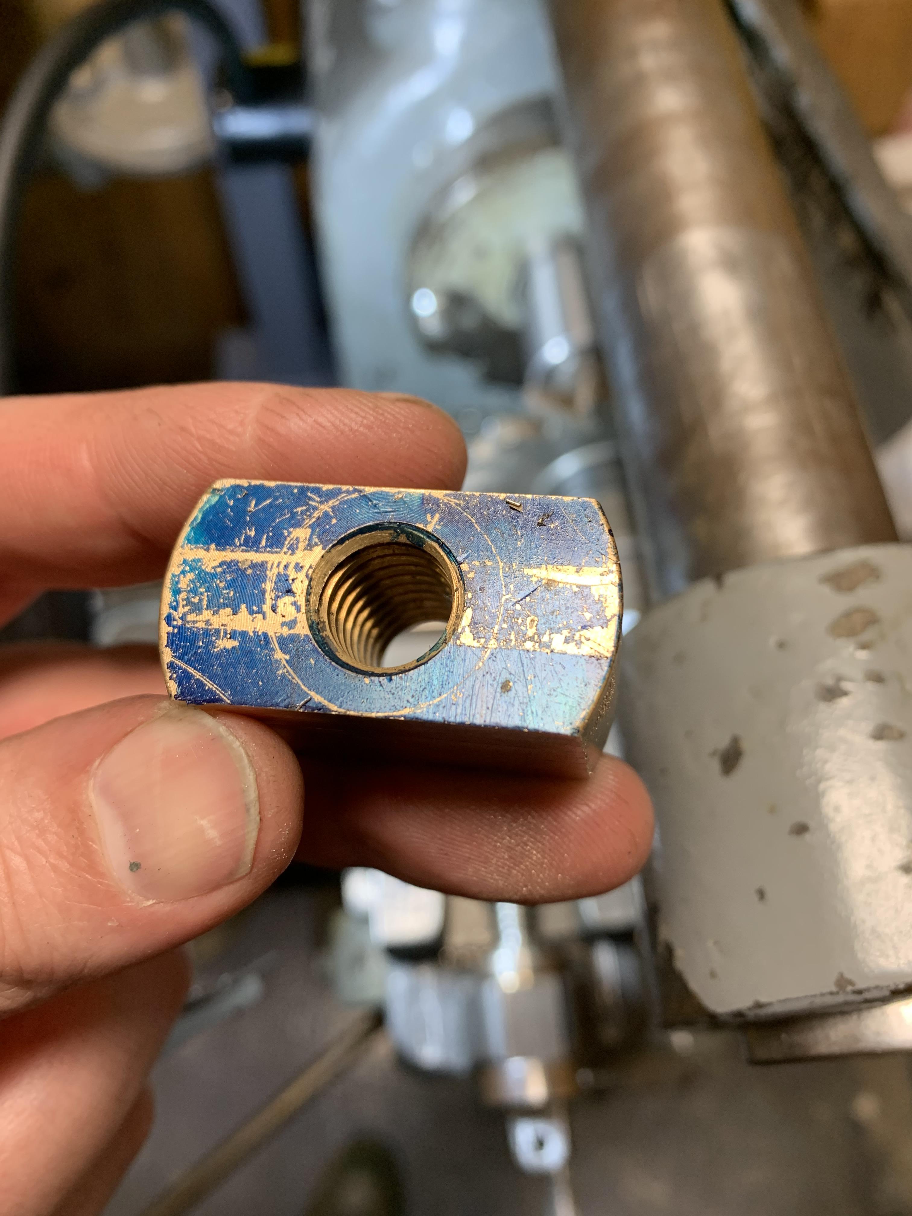
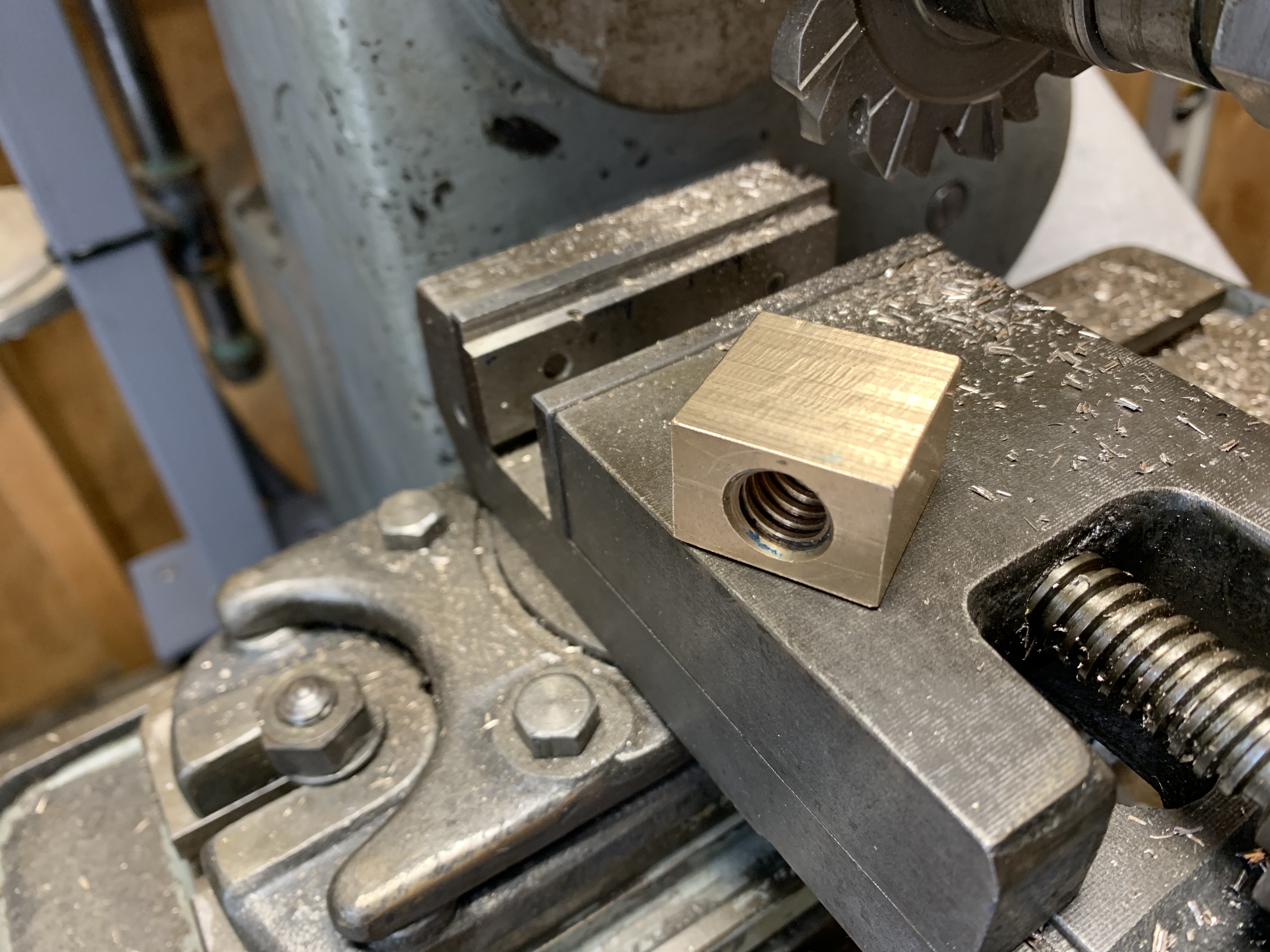
Finished the lead screw nut for the long axis of the table. I didn't spend a lot of time checking dimensions. The vise isn't trammed and there's literally nothing I trust about the mill. Also, I was in too big a hurry and didn't even check to see how far out it might be. Not all the dimensions are critical but keeping the lead screw parallel to the table is important. Unfortunately, there is about 0.008 variation from one end of the nut to the other. In this case, I may be able to get away with some shims. A proper machinist would be to fix the problem and correct the part. But I don't know how to fix the problem without buying another vise. And maybe there's still other problems that I can't see until the vise is fixed...

zG5I2Cb.jpg


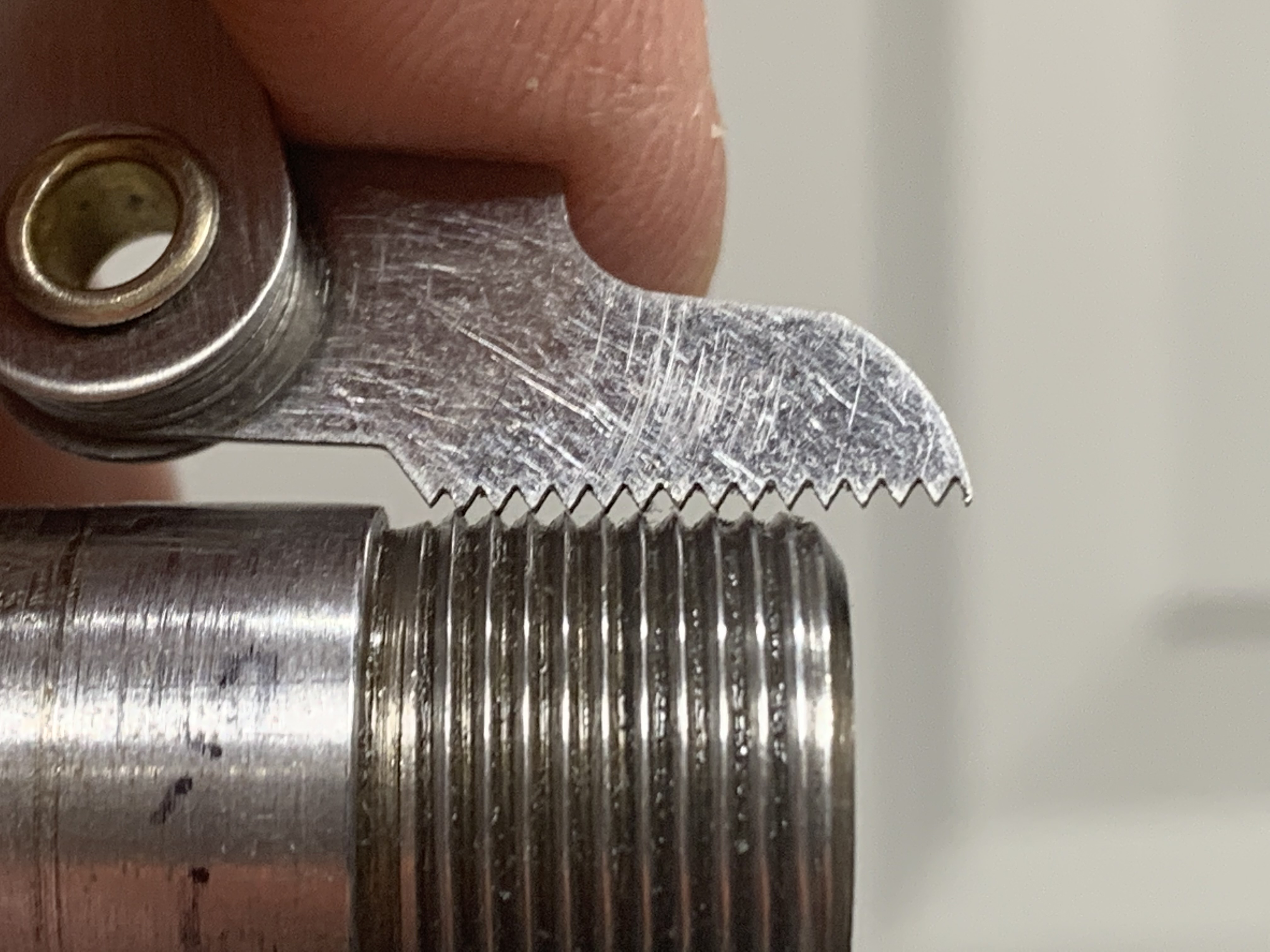
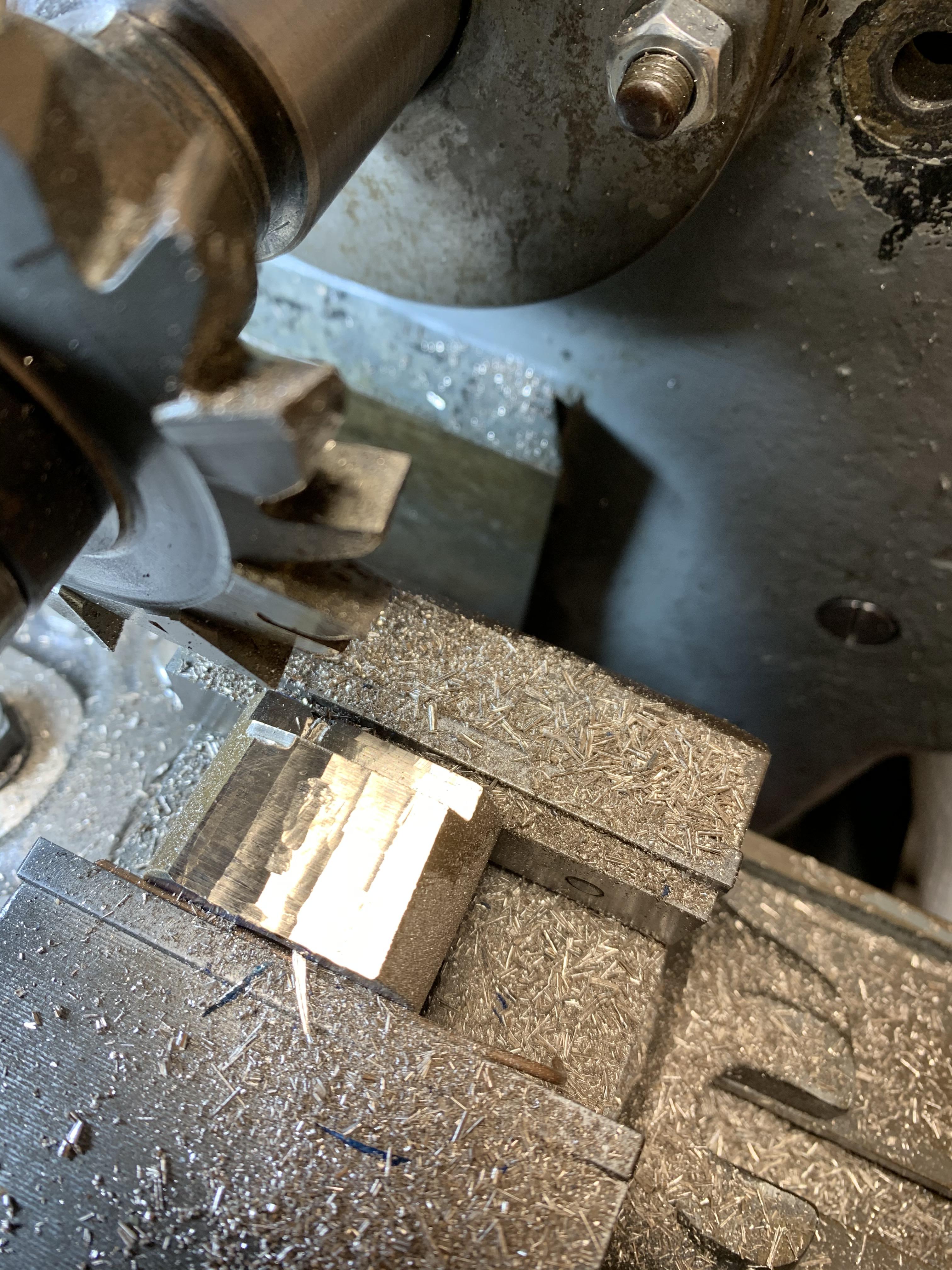
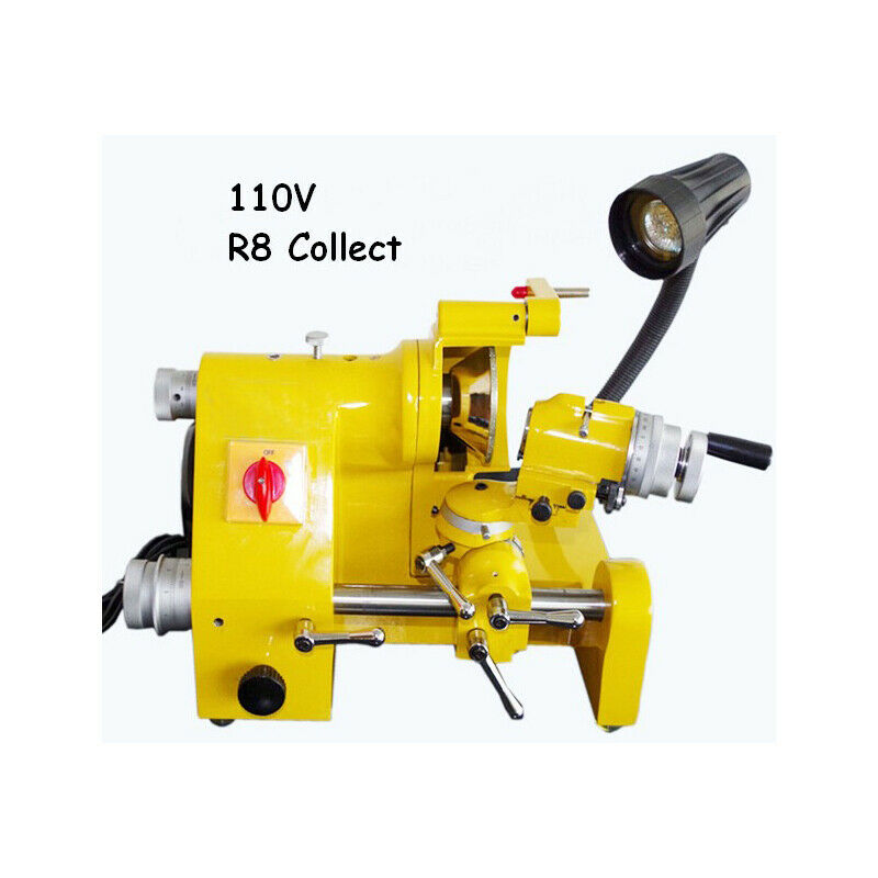
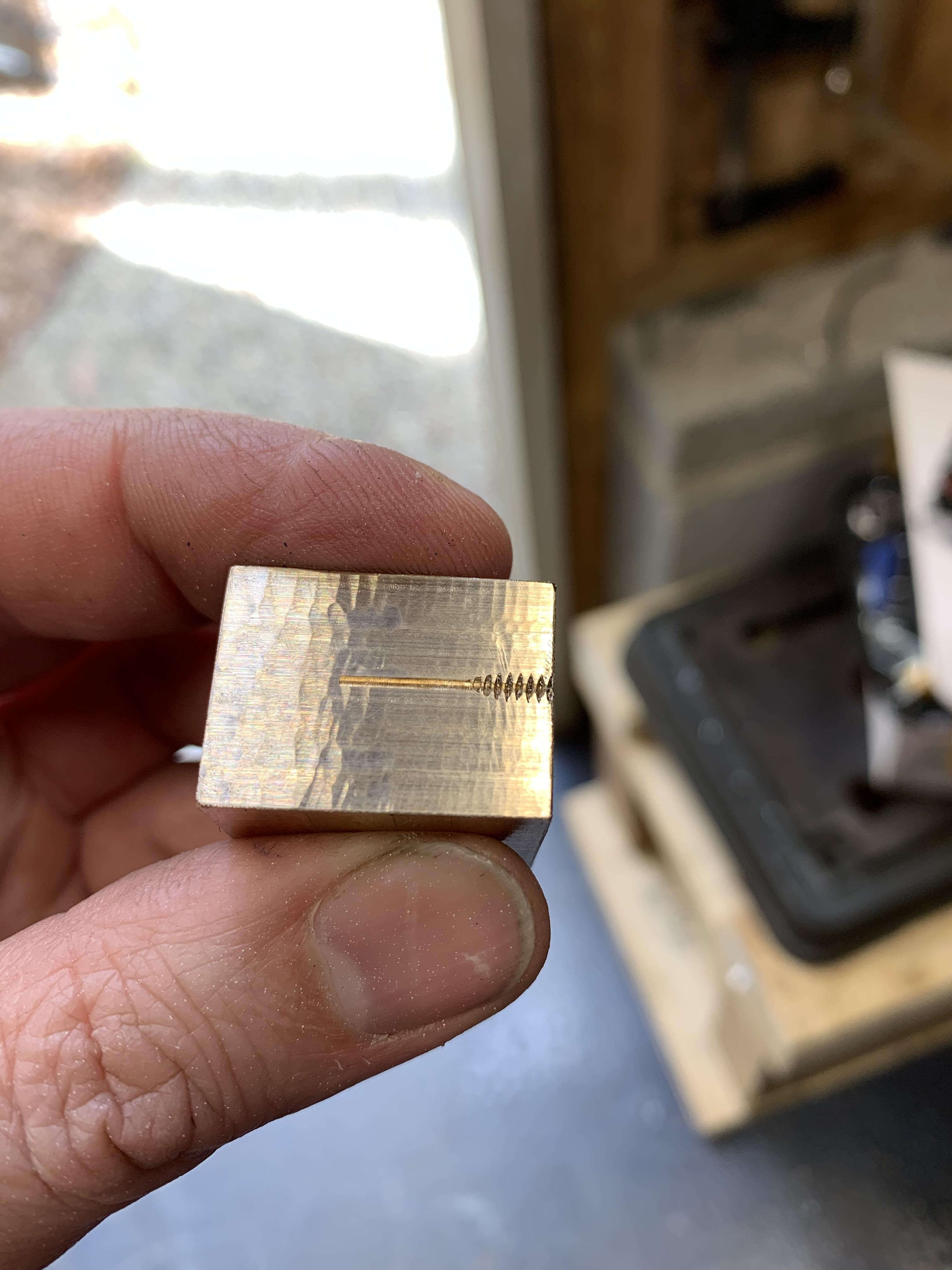
Have a look at the finish. The larger scallops are at the beginning of the cut.

AerFTCo.jpg


I am taking fairly deep cuts, around 1/4" but only 1/2 the width of the cutter, maybe 3/16". There's runout somewhere in the system so one side of the cutter, perhaps only a few teeth, are taking a larger cut. When I approach the work, the cut is quite rough. The sound and feel are a little alarming. You can see it in the finish. When the cut is deep enough that 2 teeth are in the work, everything sounds better and the finish is better.

One of my previous obsessions was hand saws for wood working. In the English tradition, one chooses the saw that has about 3 teeth in the cut. Usually you cut at an angle so it's not as simple as knowing the thickness of the stock you're cutting. In that case the additional teeth set the toll pressure. The chip load can be a big problem with wood so more smaller teeth is counterproductive. The Japanese tradition goes by the length of the saw, which is closely tied to the number of teeth. The teeth have a completely different geometry but it's all the same in the end---too many or too few teeth in the cut is a problem.

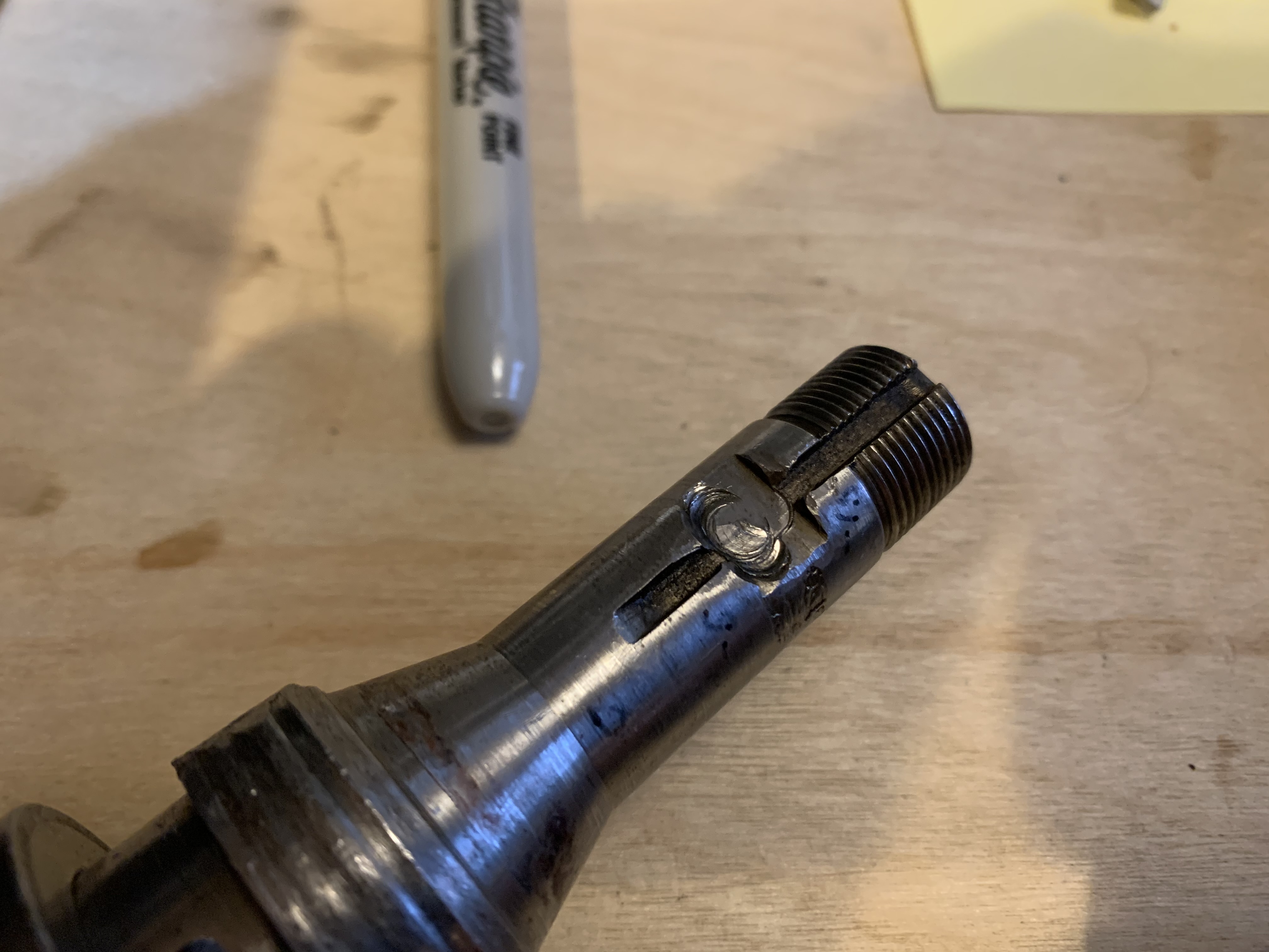
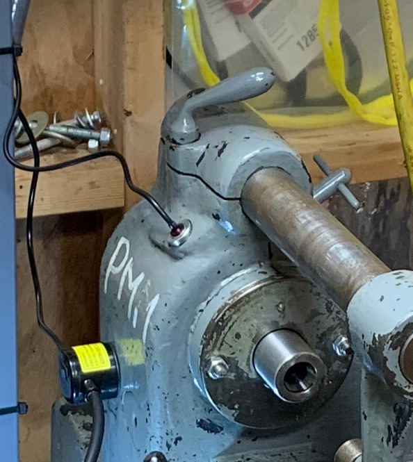
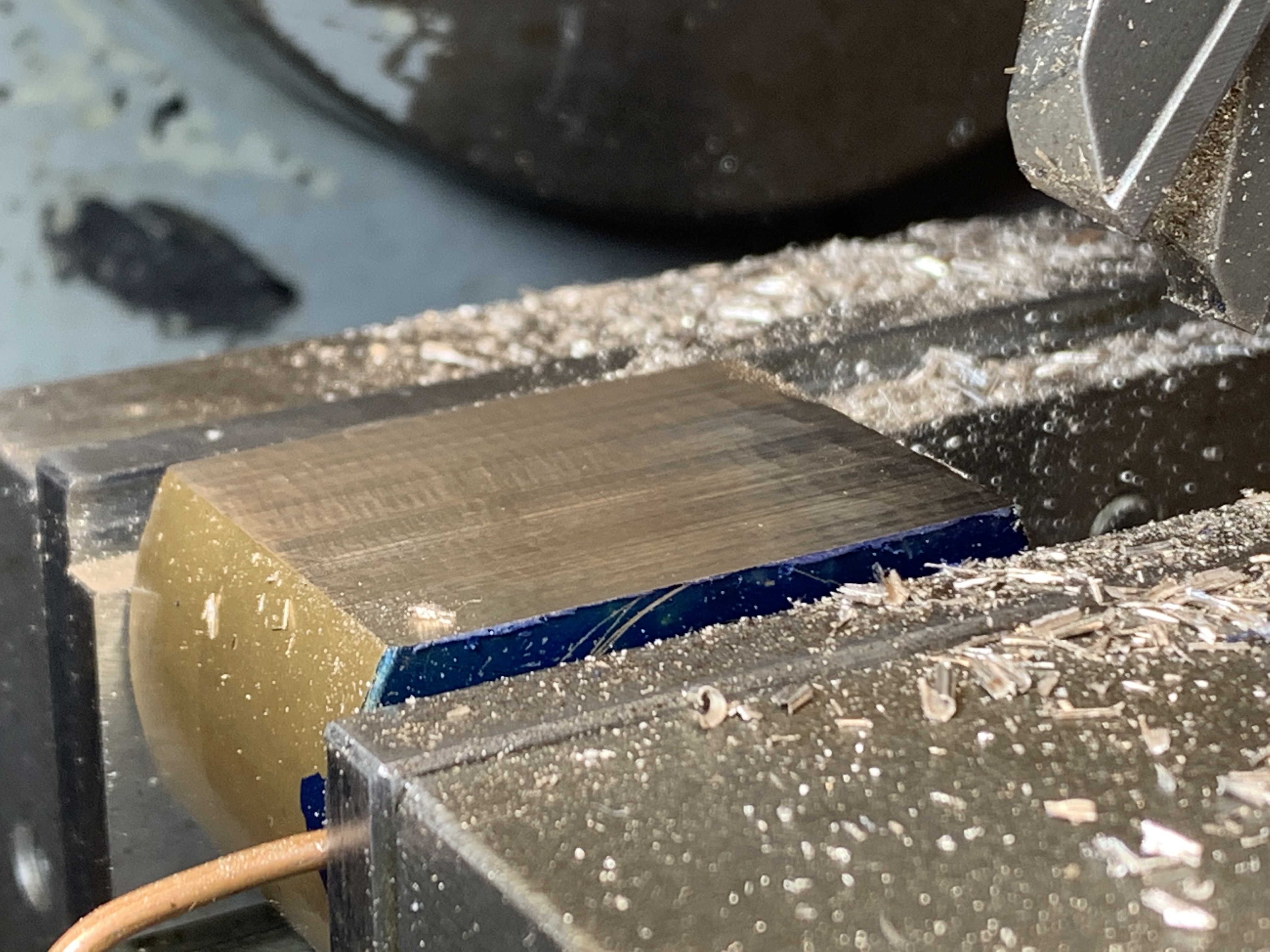
I think the sound and vibration is coming from the lever/pinion/rack that drive the long axis of the table. I can see it clattering even as I try to hold it steady. It is worse when a single tooth is in the cut. If the lash in the rack-and-pinion is causing the problem, I hope that the lead-screw feed will solve the problem.

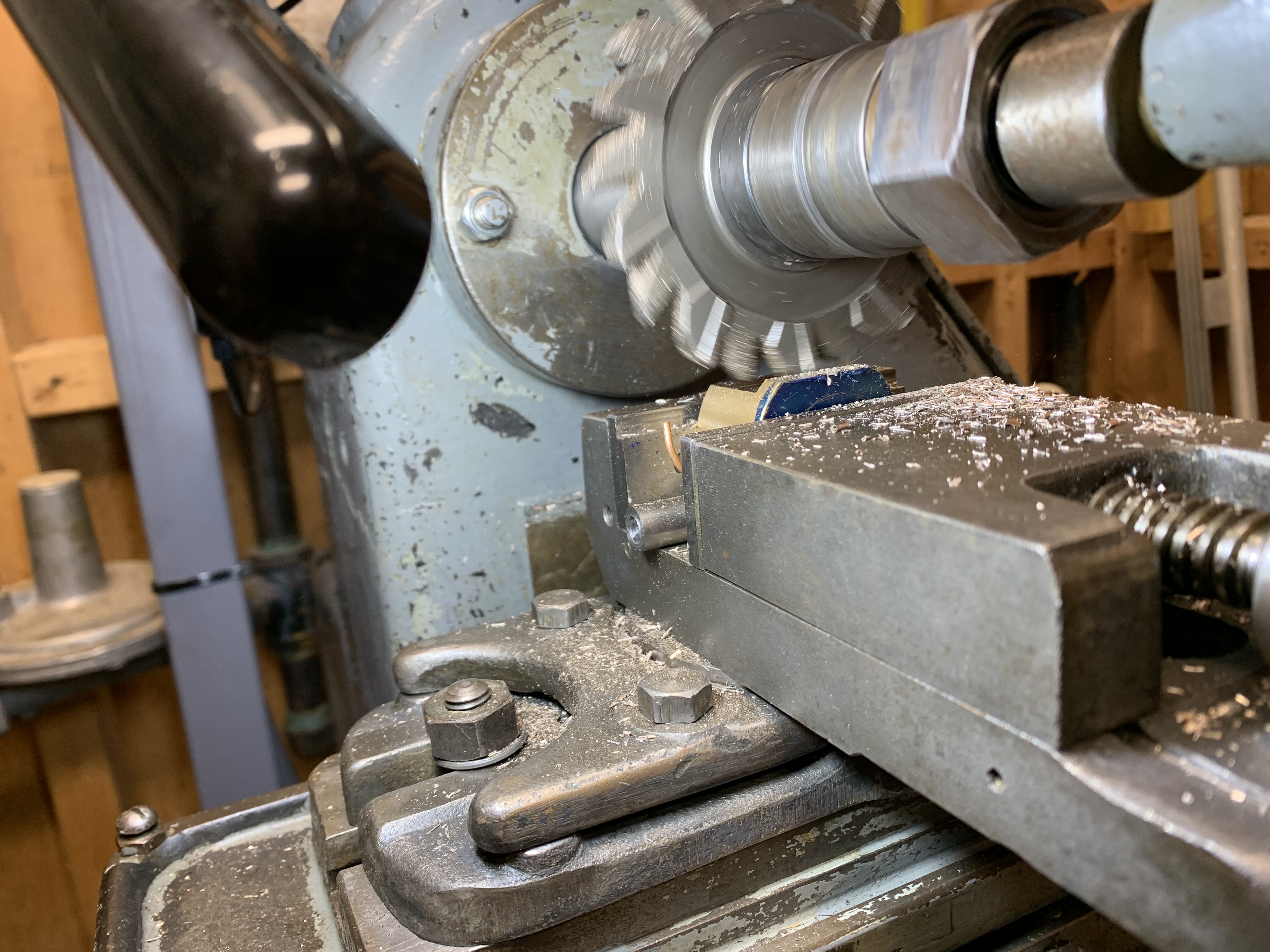
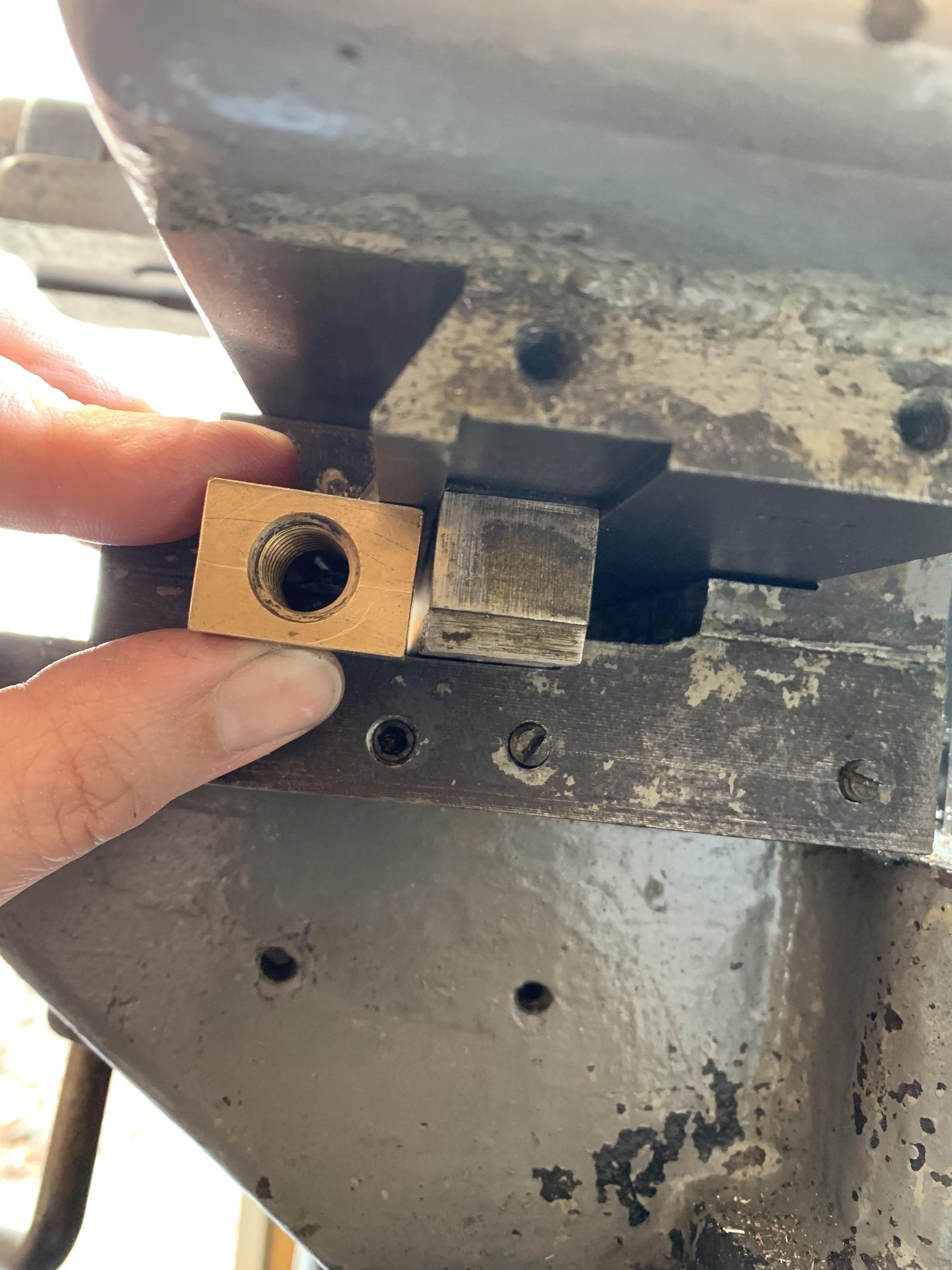
This is where the nut goes. The channel that the teeth of the rack occupy is 1" wide. I will need to file off the corners to get the nut fit, then bolt it into the saddle. Once that point is established, I feel like I can easily make end plates for the table that accommodate the screw, wherever it falls.

NRNc8Ki.jpg


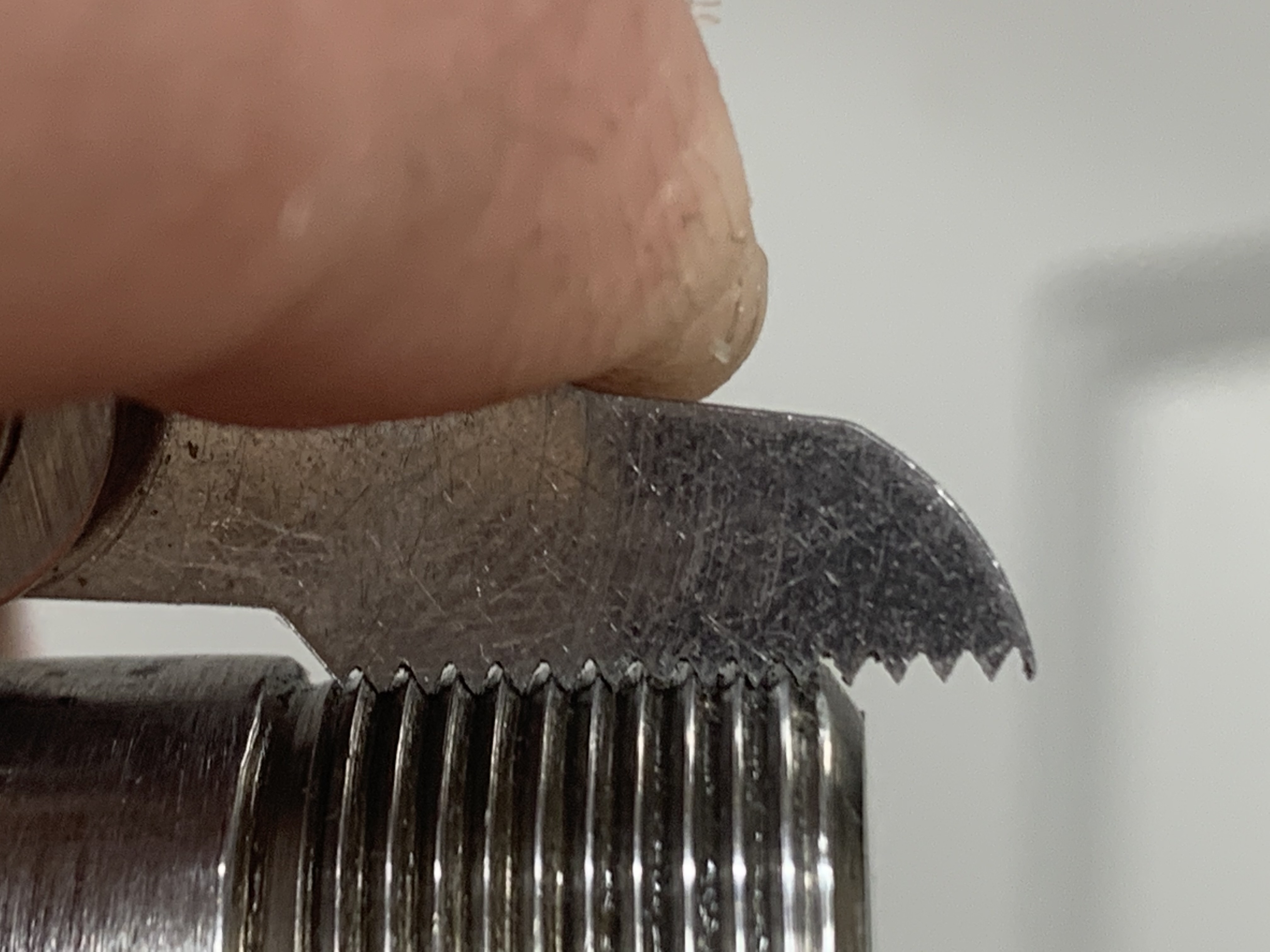
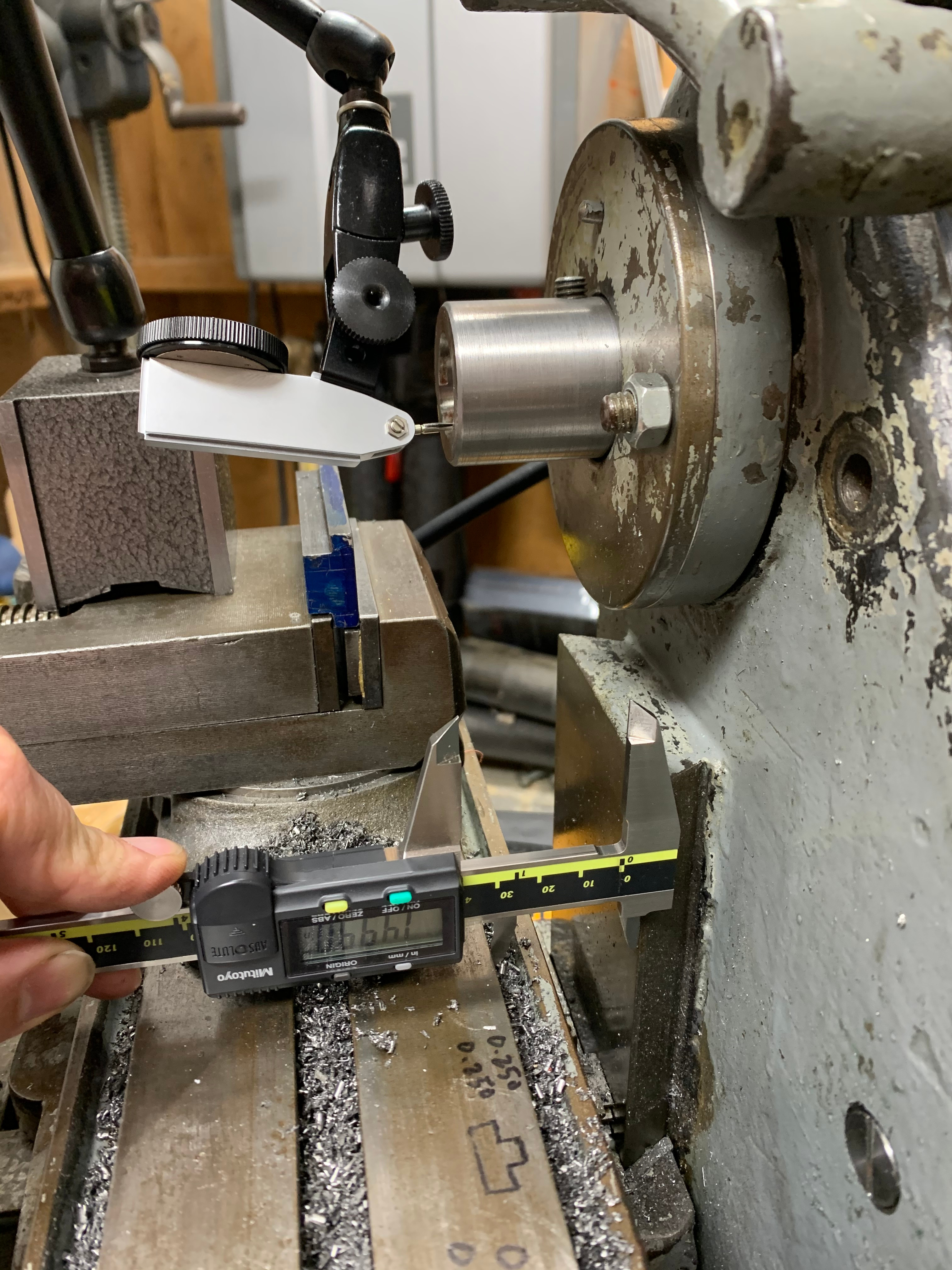
Visual check of the height of the nut. I might need to take a little more off. The rack is 3/4" but I forgot about the recess it sits in.

UL5Zkdz.jpg


In brass, the cutter definitely cuts better when it's razor sharp. Keeping it so is difficult. Using a stone, hand-held, is difficult but does work. I'm looking forward to using the d-bit grinder to sharpen cutters. I've not seen it done but I read a post somewhere (here or practical machinist) about how to do it. I also ordered the endmill sharpener, which allows the cutter to turn in a helical path. This would be mainly for sharpening slab cutters. At least, that's what I was thinking a week ago. But from my recent experience, I am no longer sure if the mill is capable of running a 1" wide slab cutter. It stalls easier than I expected---the spindle, not the motor or 15:1 transmission. So I might need to re-visit belt tension, make better pulleys, or convert to a cog or multi-V belt type drive train.

About grinding cutters, I've been assembling a list of possible uses for a universal d-bit type machine. There's probably lots of other tasks that I just don't know about.
  1. Sharpen milling cutters
  2. Sharpen slitting saws
  3. Make d-bit endmills (all 8 types)
  4. Make d-bit reamers
  5. Make dovetail cutters
  6. Sharpen endmills (ends yes, flutes maybe)
  7. Sharpen drills
  8. Make carbide spade bits
  9. Make counterbore bits from twist drills
  10. Grind tapers
  11. Relieve end mills for longer reach
  12. Grind lathe tools
 
I'm suspicious that something else is wrong with the x axis feed. Lever and hand wheel feeds have been used successfully for decades on production horizontal mills, and not just for cutting soft metals. Is there a lot of backlash in the axis? If you try to wobble it by hand, is there obvious movement? Internet wisdom says that backlash doesn't matter, but it really does if it is severe. Before expending a lot of effort on a lead screw conversion, I'd be tempted to try to cobble together some kind of temporary screw feed to test what is going on. A large C-clamp can be the start of such a test.
 
Back
Top