Kevin - A V Carroll Horizontal Mill Rebuild

I'm suspicious that something else is wrong with the x axis feed. Lever and hand wheel feeds have been used successfully for decades on production horizontal mills, and not just for cutting soft metals. Is there a lot of backlash in the axis? If you try to wobble it by hand, is there obvious movement? Internet wisdom says that backlash doesn't matter, but it really does if it is severe. Before expending a lot of effort on a lead screw conversion, I'd be tempted to try to cobble together some kind of temporary screw feed to test what is going on. A large C-clamp can be the start of such a test.

Good question. Let me check...

When I received the mill, I took apart the x-axis and cleaned it completely. I re-assembled and lubricated with way oil. The gib is tightened down as much as possible. There is a bit of stick-slip when I pull on the lever so it may be slightly tighter than necessary.

The pinion gear is held onto its shaft with a tapered pin, which was not driven home. That resulted in lash between the lever and the pinion. I've fixed that and it helped a lot. There is some lash in the rack/pinion. I just measured it now. I was going to measure lash of the table but it's really hard to move by hand. I put the indicator on the pinion and measured about 0.010" of total movement.

llXXFg8.jpg


When I'm cutting, there is perceptible motion in the table but it's hard to figure out where it's coming from. The x-axis is tightened to the point that an 1/8 turn more on the gib-adjustment screws is a problem. The y-axis is similarly tight. And the z-axis, which both x and y are on, is locked tight. Still, if I put a good test indicator on the table, I can deflect the needle 2-3 thousandths in either direction with 50-80 lb of pressure on the table. If I press in the middle of the table, the deflection is closer to 0.001". Seems fairly squishy.

After reading you comment, I finished the T-nuts. Felt similar to machining brass, actually. I was as likely to jam the cutter and slip the belts with both materials. After tightening down the vise properly, there was no difference---still super twichy and difficult to feed without jamming. I tried a smaller cutter with more teeth, which also didn't help.

w575Vjm.jpg


THEN, I measured the spindle runout. The spindle is running out 4--5 thou. This explains the trouble feeding, I think. It explains the pulsing I feel in the lever. And combined with the stick-slip of the x-axis, the feed is probably jerking, causing the cutter to bite too hard and slip the belts. From Machinery's Handbook, a few thou cut per tooth is a typical feed rate. So if I'm trying to feed normally on the low side of the cutter, when the high side of the cutter comes around, it's trying to take a huge bite. I noticed that I sometimes would get into a rhythm, advancing after the high side took a cut and slacking off a little when the high side came around again. It's 70 RPM and you can hear and feel that something is out of round.

I've already check the arbor. The arbor seems perfect, on the surface plate. BUT the spindle is a train wreck. I'm getting 0.004" runout wherever I measure---in the bore, on the spindle nose, on the taper. I removed overarm, nut, and spacers, which made no difference. I tightened and loosened the bearing pre-load but nothing changed, whatever the setting. I measured with very light belt pressure and heavy belt pressure---maybe 0.0005 variation in runout. I measured the diameter of the spindle nose with a micrometer and got the same readings all around, within a few tenths. Is there an other explanation other than a bad bearing? Seems odd that the runout is bad at both ends of the spindle.

I pulled the spindle and bearings. Both inner races are too loose and are rubbing on the spindle. There are burnished lines on all of the rollers which, in my imagination, indicates a metal chip getting jammed between a roller and a race. Probably it was a metal that was softer than the bearing components. Abrasive wear looks different---more of a cloudy effect. See the p. 47, Figure 10 in the SKF failures-analysis publication. Abrasives, if I understand it, are very hard but mostly brittle. They don't burnish but catch on the roller, pulling the article under the contact patch. The abrasive particle then breaks, making even smaller abrasive particles. But I have distinct shiny rings on my rollers, not hazy tumbling abrasive patterns.

I ordered new bearings, just in case. Not sure if that will fix the problem.


X22UQdv.jpg


AuJgLec.jpg


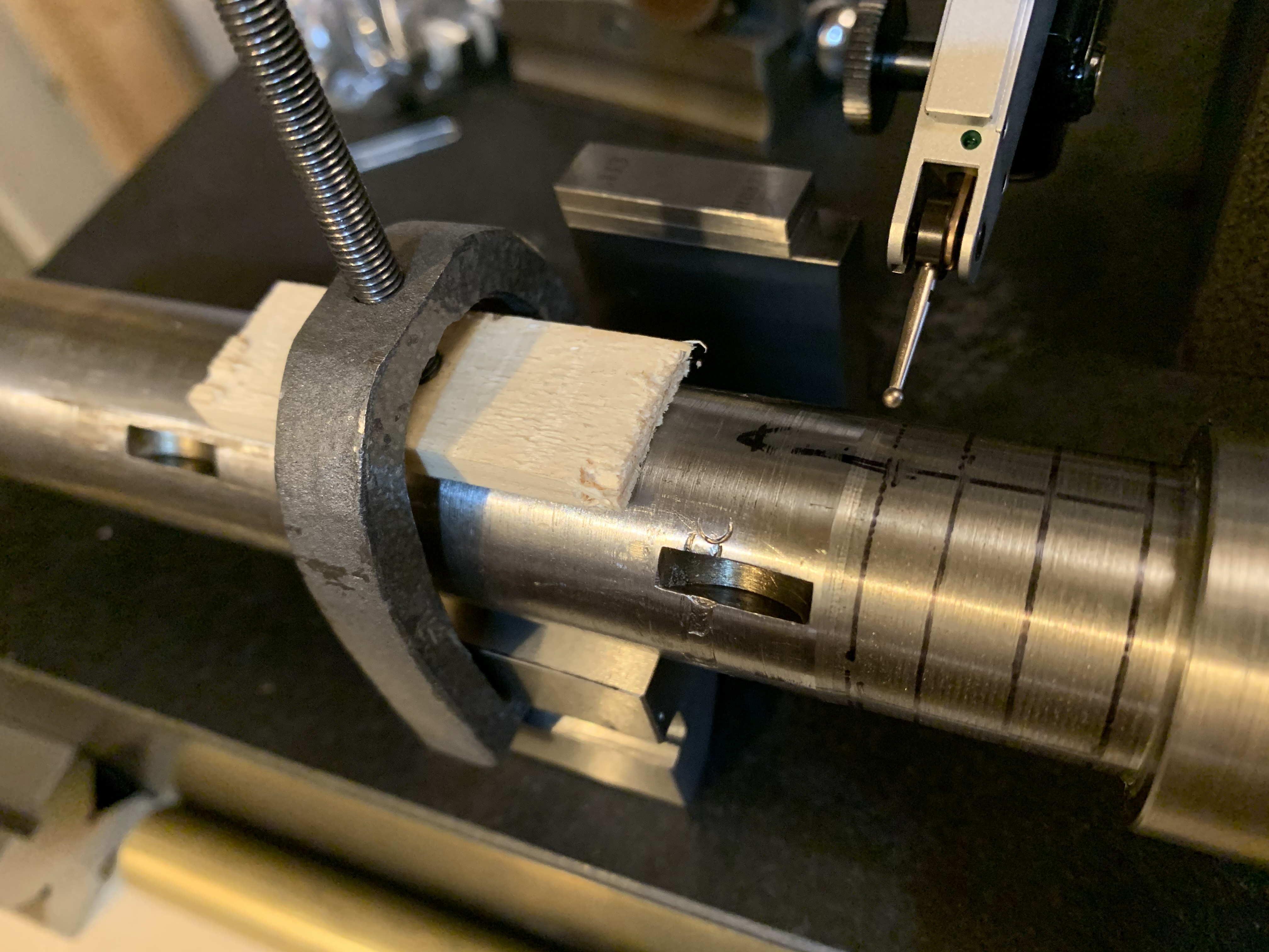
I read some more about TIR and I can't see how the bearing could be causing consistent deflection at low-speed (30 RPM). So I measured the shaft. Where the front bearing touches the spindle shaft, near the nose, the spindle is out of round. To avoid errors from the spindle is mounted, I measured it with v-blocks (wide and narrow sides) and suspended on a rod between v-blocks. All measurements gave the same result---about 0.003 deviation from one side of the shaft to the other. The other end is better. These measurement correspond to the scuffing on the inner races, too.

UAPrf4G.jpg


So now what? Shim the bearing? Make a new spindle? I'm not super confident about turning a new spindle. Haven't turned between centers before and my first single-point threading on the 9x20 was a disaster. It's a long bore, far longer than I've ever done. It would be an opportunity to change the collets... Maybe instead I could true the shaft on the lathe, make a bushing, split it, and press the bearing over the bushing.
 
Good investigation. That's an interesting question about the spindle. I'll see how much my table shakes. I think it is very little. My little horizontal mill does shake and buck if the gibs are not well snugged, though, especially when cutting with a flycutter.
 
I just checked. The x-axis is 13 thou, even with the gibs snugged. The z is even worse, with side to side shake. I have to make sure to snug everything before a heavy cut in steel. But it does work. The x movement is due to screw backlash. Part of normal operation. I think the arbor also has significant runout, but with a flycutter, it's fine.
 
I'm considering my options for the spindle repair. I thought I might get a similar bearing with a larger bore. That would give me some leeway to repair the shaft. I downloaded the Timken catalog and found the catalog numbers - 1985 for the inner race (with rollers and cage) and 1931 for the outer race. The nominal shaft diameter is 1-1/8 (1.125") and the bearing OD is 2-3/8 (2.375"). I searched for all bearings with the same outer race and found that 1.125 is the largest shaft supported. I also dug through the other types of bearings, just to see if any other bearing could be pressed into the housing. I found nothing. I went through the catalog, using the PDF search function. I used cad.timken.com to do parametric searches of the available offerings but found nothing. After looking, I realized that the repair to the shaft is the key and that any solution can accommodate the original bearing. So it was an educational dead end.

Is it practical to turn down the shaft (where the inner race sits) by 0.003--0.004 and replace the lost material with a ring of brass shim stock? If I remove little, the shims would be thin and fragile when pressing on the bearing. If I remove too much, the strength of the spindle will be compromised. An intermediate solution lends itself to cutting a precise collar on the lathe, which could then be chamfered to ease the bearing on and split (halves) to get it onto the shaft. Maybe a band clamp would be needed to keep everything in place while pressing the bearing on half way. I suppose there's no reason to use a soft metal, either. I am thinking some half-hard O-1 might be a good place to start.
 
I decided to turn down the shaft and fit it with a precision split collar.

Turning between centers is probably the way to go. I don't have a center for the spindle nose, so I tried mounting the spindle in the 3-jaw chuck. It was running out 0.005 so I fiddled around with shims and tapping various jaws for a while. It was within 5 10ths eventually but after taking a few light cuts, I measured a variation of 0.002.

VZSJk9S.jpg


It's fairly round---1.1049 one way and 1.1050 the other way. I tried measuring the runout of my cut in several ways. First, I used precision ground stones to clean up the surface. Then I rolled it on the surface plate, with the nose hanging off. Not sure if I was getting accurate results, I also tried on a v-block and in a vertical mode. All resulted in the same measurement, about 0.002 variation in the area I cut. This is measuring the same points on the shaft each time.

eyuCgzP.jpg


The vertical measurement is a little strange. I'm waiting on a snug so I can do a better job measuring vertical deviation. You can see the stand and ball bearing in the background. There are lots of assumptions with this measurement. For example, is the nose perpendicular to the shaft? Is the nose round? Turns out, it is fairly round, measuring 1.4349 and 1.4350. There were parts that could move relative to each other, non-machined services, etc. Anyway, if it didn't give me results consistent with my other measurements, I wouldn't believe any of those numbers

Well, my efforts to shim (and tap) the chuck were not successful. I think I'll need to make a large center with a drive screw. If I make it on my lathe and don't take it out of the chuck, it will be a minimum runout situation. Also, it will be a chance to check the alignment of the tailstock, another critical aspect of getting a good result.

An O-1 blank is on the way from McMaster so I can start working on the collar soon. I think I'll be grinding the inside and outside on the lathe. So I need to build a mount for the grinder...
 
I was watching Suburban Tool videos (as one does) and happened on a spindle-repair video (around 14:00). They've mounted a spindle using spiders, which they call "caps". They're using it for rough OD grinding.

Also, they measured spindles on v-blocks with a height gauge, one of the things I tried. Their v-blocks probably matched and were not purchased from Amazon. Or Shars.

3PbkDS5.png


The idea of making a cap is more appealing than making a dead center and a lathe dog. So I dug out a 2" round of 1215 and made a cap. The hole is about 1.5" and the screws are hardware-store grade 10-32 with jam nuts. It was a challenge to get everything running true. It's pretty crude compared to a proper 4-jaw chuck. Before my 3rd cut, I added brass plugs under the screws, which was a huge improvement.

PAO3A1g.jpg


For the 2nd cut, I took the lightest possible cut to clean up the shaft. I used a home-made HSS cutter that was honed to a razor's edge. After taking 2 very light cuts, I took it back to the surface plate. The measurements were difficult. After taking a set of measurements, I went over the surface with 800-grit sandpaper, which improved repeatability. Then I took another set of measurements. The measured runout was 0.002 before the 2nd cut and 0.001 after. Better but I'd like to get it down below 5 10ths.

bnDaiXg.png


I needed to improve the spider a bit and make another cut. When I tighten the screws, it rotates the work. And maybe there are other problems, hidden by my inexperience. I added brass plugs under the screws, which is a bearing material. I switched tools and ran it over the diamond stone, dressing the edge and radius. I thought I might set the gearbox for a slower feed but I ended up hand feeding. I snugged up the gibs and adjusted the tool height before making the cut.

After the 3rd cut, I took another set of measurements. I'm measuring every 90 degrees and at 4 places along the cut. First few measurements were good then got worse. I had added a v-block clamp and it may have been raising burrs on the shaft. Runout got worse. Then I stoned the shaft carefully and used a wood block to protect the shaft. The runout was comparable to the measurements before I added the clamp, Looks like I've gotten runout around 0.0005, which was my goal. I think I'd need to set up an OD-grinding fixture to do better on my equipment.

TZU2yZM.png


5tRP9zr.png


Here's the final measuring setup. Had to use a single v-block because none of mine match. It wasn't balanced so I had to press it down while measuring. The wood block protects the shaft and the gauge blocks are there for sanity. When things are weird, it's a psychological relief to be able to check your indicator. This is the BesTest and it's better than the cheap meters. But having taken several hundred measurements tonight, I see that it is not perfect and also that my stand is just not adequate for 50-millionths measurements. Every time I bump the indicator, it's got to be checked. Even approaching the work rapidly can mess it up. Approaching the work by pushing or pulling gives different results. A certain amount of tapping was needed. Several times I thought something was wrong but the indicator settled into the expected answer after minutes. Maybe i just turned away and the vibrations from the house helped the meter overcome internal stick-slip. Whatever it is, these measurements are harder than I expected. I think the last set of measurements took me 4 hours

oh8ApbS.jpg


I took some measurements on the live center in the tailstock. Runout wasn't great. Maybe I should flip the part around to cut a groove for the rear bearing repair. Near the chuck, it's easier to adjust.

Thinking about the sleeves I need to make for this repair---they will be challenging pieces. I want to cut the OD to size and trepan instead of the usual drill & boring bar routine. But the dimensions are so critical and I'm not sure I can deal with adjusting the ID after cutting that part off. Can't measure it accurately until it's off. I might be better off boring out the center because then I can use telescoping gauges and mics. Adjusting dimensions seems easy while the sleeve is attached to the stock. Still thinking about how to do that. And how to split them... They'll only be 1/16" thick and 3/4" wide.
 
I've machined the spindle OD down by 0.020. I'm going to try to press the bearing over a piece of shim stock ALTHOUGH it is a ridiculous plan. I've slept on it a few nights... Still, I've already put some work into it and it's inexpensive. Well, I bought a Palmgren 2-ton arbor press so I guess it's not as inexpensive as I expected. But a man needs a press. I've needed this for 15 years.

I thought about getting a new spindle machined. I might need to make a new arbor, to match. But I'm going to try the shim method first.
 
One quote for a new spindle was 600 $, the other was 750 $.

On the path to 3C collets, I need a pin to prevent the collet from rotating. There was a 5/16-18 hole in the spindle---perfect. So I purchased "alloy" dog-point set screws from McMaster and used the D-bit grinder to turn the point down. It was fairly hard material. Nice orange sparks. This is the first job I did with that D-bit grinder. The arbor isn't tapered so it's main use is a 320-grid diamond face wheel.
IMG-3209.jpg


To hold the screw, I made an aluminum adapter, turned to 0.501 on the OD and threaded it for 5/16-18. The first screw protrudes and the one behind it jams everything securely. Unfortunately, it's not a machinist fit on the threads (maybe it's my cheap taps) so the tip didn't quite grind symmetrically. Very close. Close enough for this job.
IMG-3210.jpgIMG-3211.jpg


The set screw is glued in with medium Loc Tite 242. I wanted the head of the screw flush for safety reasons and vanity. To get it all to fit, I ground the tip shorter.
IMG-3212.jpgIMG-3214.jpg
 

Attachments

  • IMG-3213.jpg
    IMG-3213.jpg
    1.2 MB · Views: 3
  • IMG-3208.jpg
    IMG-3208.jpg
    1.5 MB · Views: 3
Well, I'm back to thinking about how to adapt the 3PN spindle to 3C. I was originally going to make an adapter (as one does) but I'm not 100% confident that I can do it.

Another option is using a MT3 -> 3C adapter. The MT3 end is larger than the current taper. If I start with this part, I can skip a lot of the work. But will it be too hard to machine on the OD? If it's hard, all I have is some brazed carbide tooling---no CBN. It would be too much material to remove with a makeshift toolpost grinder.

Screenshot from 2021-08-22 00-01-05.pngtaper_adapter.jpgmorse_taper_dimensions.png

Here are a few possible adapters. The first is... low profile. Difficult to make. The second design, with the flange, is probably more realistic.
I'll print them in PLA first and then see about making one in O-1. I'm thinking mill within a few thousandths, harden, and then grind the OD on a 3C-tapered arbor in the lathe. Then glue the adapter into the mill's spindle and grind the ID in situ. Will need to mount the mini lathe compound on the table...

I had previously purchased some parts to make a tool-post grinder. But I ended up buying the Black Eagle Precision unit on eBay. Mounts right up to the AXA tool post. A proper hobby machinist should drop everything and spend 6 months building an awesome grinder. I don't have a working mill so I thought I should just buy the grinder and get on with it.

adapter_3pn_to_3c_short_section.png
adapter_3pn_3c_long_section.png
 
What an adventure, keep your positive attitude and you will get there.
 
Back
Top