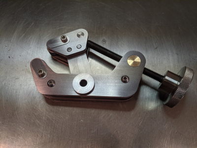
Knurling tool build

It was very difficult to machine all these parts to get optimal spacing for the knurl wheels. My original idea of a hollow axle with a screw through it solved that issue and was workable but not ideal. It required partial disassembly of the tool just to change a knurl. That would be very cumbersome and I am lazy.
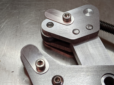
I decided to add precision spacers adjacent to the knurls to maintain the arms at .380". These are just hollow tubes so they are easy to nail the tolerance required.
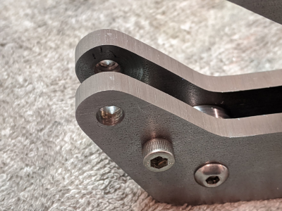
Here you can see one of the new spacers retained by a 10-32 screw.
1585880854833.png

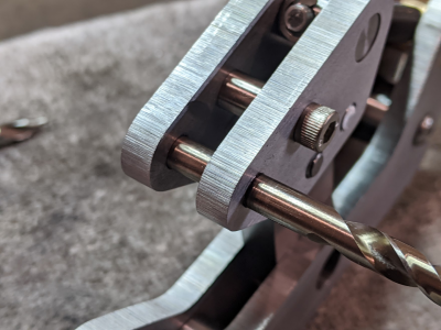
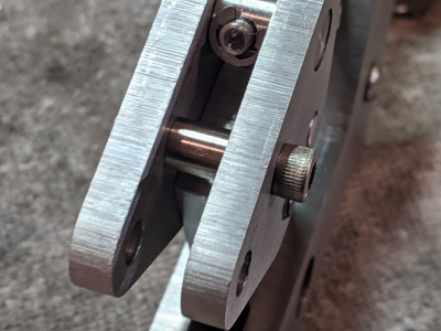
This allows me to use a solid axle made from an old 1/4" drill.
You can see that I clearance drilled one side for the axle. The other arm has a hole that only goes half way through at full diameter. This will allow me to slide the axle in and hold it in place with a small cover plate. There is no significant lateral force on the axles. (I hope)
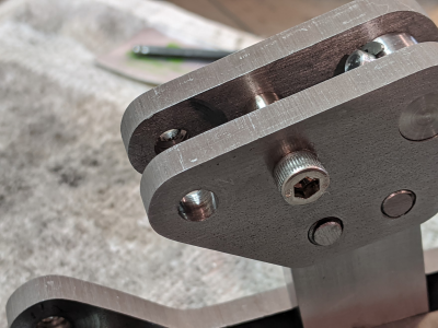
1585880988181.png

1585881001882.png

1585881015186.png

I just need to cut sections from that drill to act as axles. The cover plate with be elongated and held in place by the same #10 screw that holds the precision spacer. To change a knurl you simply loosen the #10 screw, slide the cover plate aside and slide out the axle.
I hope this it the final version but some testing is in order!

Robert
 
looks beautiful RWM and fantastic knurls too! If you want a way of retaining the axle, one thing I had planned to do with mine (when I build it!) is a small set screw intersecting the axle bore. You could even turn down the end of the set screw to make a pin. Then grind a notch in the axle to line it up with the setscrew. That way the axle can't move around but it should be straightforward to change knurls. Won't take up any space on either side of the side plates either.

I've also seen little swing down latches used, that clip into a circlip groove on the end of the axle. That would be even simpler to change knurls with..
 
  • Like
Reactions: rwm
Finally had a chance to go through this thread, Robert, and I should have read it earlier. I use a very quick and easy method to hold the pins in my knurler that I actually got from Guy Lautard's First Bedside Reader. I've been using this set up for over 20 years and my pins (drill blank) have no significant wear and the wheels can be changed out in a few seconds. You might consider it. See below:

pin1.jpgpin2.jpg

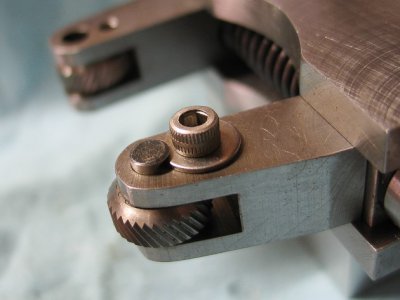
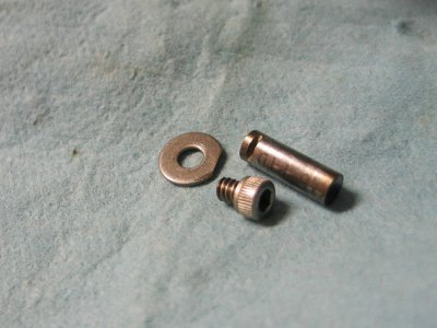
The pin hole in the arms is a through hole, reamed carefully for the 3/16" drill blank. Each pin has a 0.04" deep slot cut in one side with an abrasive wheel. A #6 stainless washer has a small flat ground on one edge that fits in the slot, and the washer is held in place by a 6-32 SHCS. This screw has never come loose, ever. To change wheels, just remove the screw and pull the pins. Takes just a few seconds to do.

I have a writeup on my knurler that I wrote over 15 years ago. I've been meaning to polish it up and post it but life has been hectic. This info is in that article so I should get off my butt and finish editing it. Sorry for being so late on this.

I noticed that your knurl in post 117 shows a tapering depth of pattern. That is probably due to the tensioning bolt loosening as you traverse down the knurl. Put a jam nut on it and lock it down before knurling and that should handle it.
 
Matt- I though about doing it that way but I am terrified of 4-40 taps! I suppose I could go to #6.
Mikey- thanks for posting. That does look like a good idea. I have Guy's book. I will look back through it.
Robert
 
Last edited:
Well that was fun.
Well done RWM. Beautiful work.
 
  • Like
Reactions: rwm
Matt- I though about doing it that way but I am terrified of 4-40 taps! I suppose I could go to #6.
Mikey- thanks for posting. That does look like a good idea. I have Guy's book. I will look back through it.
Robert

ah, you'll be fine. 2-56 and 0-80 are where things get crazy :) A good spiral point tap will work wonders and you can always go up a drill size or two (say from 42 to 40) to reduce the cutting forces. It's not like high thread engagement is needed.

Mikey's version looks neat too. If you want to outfancy him, you could relive the washer on one side so you simply have to rotate it out of the way with the bolt loosened to remove the axle.
 
...or for that matter use a plate that rotates into a slot pivoting on the #10 screw that is already there. Hmmmm.
 
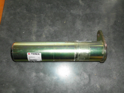
How bout something like this. Pin with plate attached like they do for heavy equipment?

1585939950039.png
 
I think I am finished!
I left one of the holes open in the first pic so you can see my solution.
1585960226270.png

1585960241324.png

It is now super easy to change out the knurls. If the axle sticks a little you can push it out from the other side.
I will update the prints soon.

Robert

EDIT: the only potential problem I can see is the axle rotating in the housing and wearing the arms. Mikey/Guy's solution would prevent that. I will have to keep an eye on this and see if I think that is happening.
R
 
Last edited:
Not finished! The doggone axles rotate during use. Not a lot but I suspect it will be a problem over time. I also looked at the write up in Guy Latard's book. Damn shame 'cause I like the way it looks! There are a couple of options here:

1. I can spot weld or TIG weld the tabs I made above to the ends of the axles. I could weld them "in situ" so the alignment will be perfect. (Weldo solution)
2. I can cut the tabs shorter and have them fit into slots in the axles. (Mikey solution)
3. I can cross drill the end of one arm and put a #6 set screw (or #8; which is less likely to break?) holding the axle on a flat. (Matt solution)

I believe all of these solutions will work. I am really torn about which route to take. #2 will involve new axles. #3 may be the most elegant. #1 is probably easiest but may look funky.
This has been an interesting journey although more complicated than I imagined. I really appreciate all the interest and suggestions along the way!
Robert
 
Last edited:
Back
Top