- Joined
- Nov 16, 2012
- Messages
- 5,596
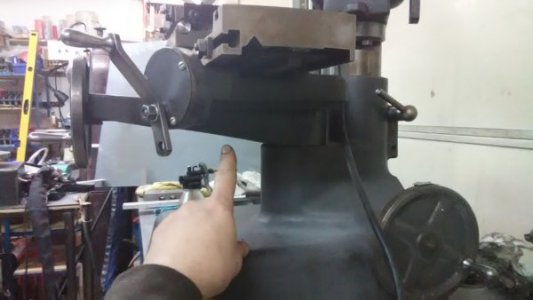
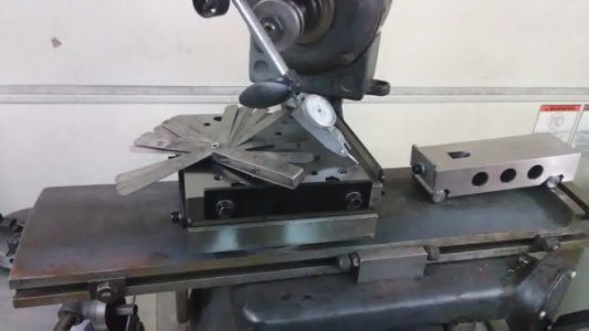
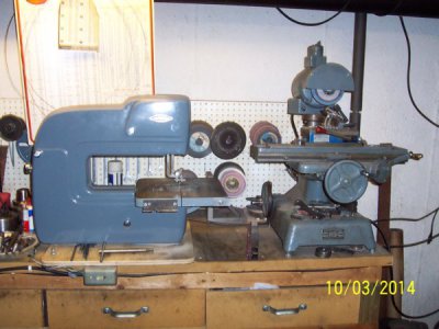
Perhaps you've seen this from other photos... It's a KO-Lee cutter grinder. It's a good platform and the table and all mechanisms are in excellent condition. I don't think this machine was used much in it's lifetime as there are very few signs of wear (hardly any at all really).
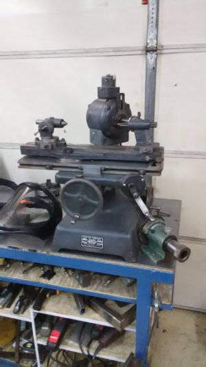
The motor is the weak link. The bearings are going bad and vibration can be felt in the short shaft. The long shaft is OK. The seller told me about this when I got it. I'm guessing someone bumped a wheel really hard and damaged the bearing on that side.
Anyhow, I once had a B&S #2 surface grinder but, sold it a few years ago. It needed too much work. It took up too much space, and I rarely worked on parts more than a few inches in size. Also, the things I make do not need sub-ten-thou tolerances. I've used the KO a couple times to do some grinding on small parts within a half-thou and it works out fine. My plan when I sold the B&S was to modify the KO-Lee to handle the simple grinding tasks that come my way.
The time as come...
I'm tackling this in a couple ways and doing the work simultaneously as I go. The plan is to address a travel issue with the KO. It's got about a 12" horizontal travel which stays true the whole way. The vertical travel is about 4" and falls-off at the extremes. I'll see what I can do about that. The other idea, is to remove the old motor and replace it with a small 3 phase and design a new spindle. The spindle design will just be a larger version of the tool post spindle I dreamed-up and posted here several years ago. It's proven to be a very good design but I want to improve a couple things to handle heavier grinding wheels possessing more rotational energy.
This will be an ongoing project that I hope to finish by spring.
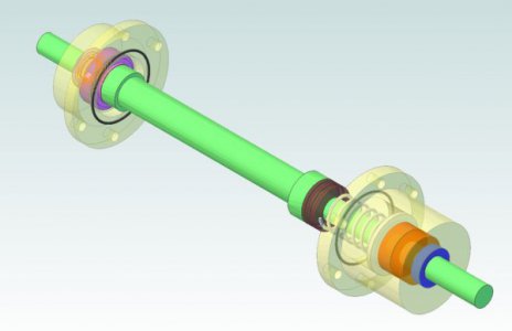
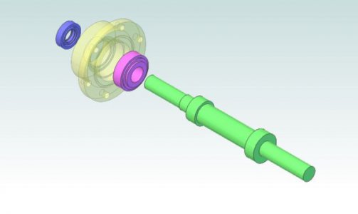
The drawing for the spindle is being recreated from the ground up. Here's a sneak preview. The design is still in my head and no dimensions are shown because I'm still making rough measurements of the KO-Lee platform and also, I have not settled on a convenient way to terminate the business end of the grinder shaft. Kicking about 3-4 ideas around. Here's what we have so far. You can upload the .pdf and see it in 3D.
As with the last project (https://www.hobby-machinist.com/threads/bull-nose-live-center.64859/) all the machining shots along the way will be shown and described (so you can butcher-up metal just like me).
Regards
Ray C.

The motor is the weak link. The bearings are going bad and vibration can be felt in the short shaft. The long shaft is OK. The seller told me about this when I got it. I'm guessing someone bumped a wheel really hard and damaged the bearing on that side.
Anyhow, I once had a B&S #2 surface grinder but, sold it a few years ago. It needed too much work. It took up too much space, and I rarely worked on parts more than a few inches in size. Also, the things I make do not need sub-ten-thou tolerances. I've used the KO a couple times to do some grinding on small parts within a half-thou and it works out fine. My plan when I sold the B&S was to modify the KO-Lee to handle the simple grinding tasks that come my way.
The time as come...
I'm tackling this in a couple ways and doing the work simultaneously as I go. The plan is to address a travel issue with the KO. It's got about a 12" horizontal travel which stays true the whole way. The vertical travel is about 4" and falls-off at the extremes. I'll see what I can do about that. The other idea, is to remove the old motor and replace it with a small 3 phase and design a new spindle. The spindle design will just be a larger version of the tool post spindle I dreamed-up and posted here several years ago. It's proven to be a very good design but I want to improve a couple things to handle heavier grinding wheels possessing more rotational energy.
This will be an ongoing project that I hope to finish by spring.
The drawing for the spindle is being recreated from the ground up. Here's a sneak preview. The design is still in my head and no dimensions are shown because I'm still making rough measurements of the KO-Lee platform and also, I have not settled on a convenient way to terminate the business end of the grinder shaft. Kicking about 3-4 ideas around. Here's what we have so far. You can upload the .pdf and see it in 3D.

As with the last project (https://www.hobby-machinist.com/threads/bull-nose-live-center.64859/) all the machining shots along the way will be shown and described (so you can butcher-up metal just like me).
Regards
Ray C.


