Lathe Tool-height Setting Gauge

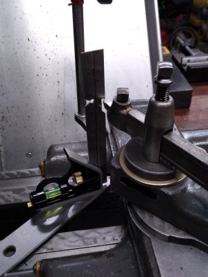
The height adjustment screw is 1/2-20, it’s locked in the base with a set screw, and the upper sleeve has a nylon-tipped set screw to lock it in position once adjusted.

View attachment 234565


.

David,
I'm getting ready to attempt a similar project and have a newbie question about the design. Regarding the 1/2-20 adjustment screw - why is this done with a screw and set screw as opposed to machining the 1/2-20 thread as part of a solid body base. I realize there are often multiple way to accomplish the same thing just trying to understand the pros and cons of the choices.
Thanks,
Mark
 
I'm getting ready to attempt a similar project and have a newbie question about the design. Regarding the 1/2-20 adjustment screw - why is this done with a screw and set screw as opposed to machining the 1/2-20 thread as part of a solid body base.

Hi Mark,

As you mentioned, there are a lot of ways to skin this cat. Initially I thought I'd turn the height adjustment thread integral to the base like you said. But I had on hand a few long 1/2-20 stainless steel bolts from another job. I asked myself "do you really want to try threading stainless when you have this other already threaded stuff hanging around?" and the answer was "no". I don't know how much experience you have threading 316 stainless, but I can tell you it's challenging. That material is tough and tends to be gummy to a point that it tears rather than cuts. So I decided to simply part-off the hex head on a bolt and use that as a threaded rod. You could also use 1/2-20 threaded rod like this: https://www.mcmaster.com/#90575a333/=195q8v8 Securing that threaded rod in the base could be done a number of ways - I decided on a set screw, but high strength Lock-tite would be fine too. If you're going to build this, it's important to use a spring wave-washer on the socket-head cap screws that secures the rotating top in order to allow it to rotate but to keep it registered flat to the top surface. I used these: https://www.mcmaster.com/#92168a107/=195q771

Hope this helps. Post photos of your results please.
 
David,
Thanks for the advice - I have not attempted to thread stainless - doesn't sound like a lot of fun. That's a good tip on the spring washer. Hopefully I'll get some shop time this weekend - I'll definitely post some pictures when I get done.
Mark
 
Very nice… I need to make one for each lathe…

Another project added to the list… but this one goes to the top…
 
That's beautiful work.
I threw one together in a few minutes that looks like the first one that @jbolt pictured. The only difference is I used two pieces of scrap steel to indicate the height, so that I could set the center on inverted tools.
Now, the question I have is how much difference does it make. We can negate getting the tool too high, 'cause then you're just rubbing the side. But, how does it affect tool wear or finish if the tool is one thou too low, vs three, vs ten?
I do know that if you get the tool too low, it will pull the carbide tip right off down to the middle of the chip breaker groove.
When the cutting tool is lower than the spindle axis, the material being machined will try to climb up on top of the cutting tool causing chatter and bad surface finish. Precise tool height is the most critical with parting operations. See attached. A parting tool that is 0.002" or more lower than the spindle axis will likely chatter, the insert can fracture ruining the part in the process.
 

Attachments

  • Parting on the Lathe - Good Practices 7-2022.pdf
    3.5 MB · Views: 39
David I really appreciate this post. I had already made a "practice" version of this tool and was struggling to figure out a precise way to adjust it down to height. I didn't have the tools for your exact method, but I did have a piece of .500" rod, a collet chuck, and a .250" block. I was able to get the height gauge within a .001" or so (I believe, but maybe .002") by stacking the tool height gauge on the block and using a parallel and back light to look for a gap.
 
In case you guys want to see how the other half lives.... One day I'm gonna stumble on just the right piece of brass for this. No idea why I'm stuck on brass, it's gonna take years to get enough wear on it to where it doesn't look scratched up... In the mean time, I just hang my head in shame and make do with one of the first tools I made for this lathe. I had this little combination square from the hazard fraught store... The casting has three machined faces, the 90 degree corner is not 90 degrees, the 45 degree corner is not 45 degrees, nor is that face 45 degrees to either one of those faces, and with the the scale locked in, it doesn't rest in any particular relationship to any of the three faces. Aside from that, it's a pretty nice square. :) It was a shame to carve it up. The bubble level is a little bit close to accurate on the face it sitting on, so there's that... The V notch goes on a center in the chuck or the tailstock. There was no measuring to make this, just iterating with a hand file until it worked.
 

Attachments

  • IMG_20221212_172149388.jpg
    IMG_20221212_172149388.jpg
    205.8 KB · Views: 43
Back
Top