Learning how to use my TPACtools DRO on my Bridgeport

Technical Ted

H-M Supporter - Gold Member
H-M Supporter Gold Member
Joined
Nov 5, 2016
Messages
1,419
I thought it might be beneficial to post what I’m learning about using my TPACtools 3-axis DRO on my Bridgeport mill to aid others that might be trying to figure theirs out. I encourage others to add their experiences as well so we can all benefit and learn from each other. Some of the basic functions are fairly straight forward and intuitive. Other features, not so much. So, I thought this might be a good place to share what we’ve learned so everyone can gain from it.

The first thing I experimented with was the use and functionality of the SDM 200 coordinate group. I can see where this is a very useful feature especially for those of you who do a lot of production repeat work. With 200 memory points for storage you would have to maintain a look up sheet to identify each location and also the part’s ABS locations. It’s important that you use the same ABS zero locations when repeating a part or your SDM locations will be off. For a hobbyist like me, where this feature would come in handy is if I had, for example, 4 hole locations that I needed to spot, drill, counterbore, then chamfer and wanted to minimize tool changes and move from location to location performing an operation on each of the four holes before turning off the spindle and changing the tool. Since I probably wouldn’t be repeating this job on a later date, the 200 memory locations are way over kill, but to others could save a lot of time and repeated calculations.

To get to the SDM storage locations press the SDM button. The display will show “SDM NO”. Press the storage number you want to use and press the enter key. After displaying a location you can use the up/down arrows to move between storage locations.

There are two ways to enter/set a SDM location. Remember, if you want to repeat this part later, set an ABS location before setting SDM locations and record in your records where that ABS is set:

  • By setting the current location as a SDM point. This is simple enough, just move to the location you want then zero the axis at that point. The SDM display will be set to 0 for each axis you zero. Any axis not zeroed will remain whatever is was.
  • By setting a Cartesian location as a SDM point. This is a little bit less intuitive but makes sense when you think more about it. When you enter a location by entering values in lets say X & Y you are actually setting your current relative position in relation to the SDM location which will be set as a datum point of X0 & Y0. You don't enter the moves you would have to make to get to the SDM location, you are actually entering the moves you would have to make to get to your current location if you were sitting at the SDM’s datum location (since the SDM’s location is 0,0 and your current location is relative to that). I’m sure I’ve confused everyone, so here’s an example.
We are going to use Cartesian coordinate system so if your current spindle location is in the center of a rectangular part, a hole to the upper right (1” up in Y and 1” over in X from your current locatoin) would be an incremental move of X=+1.000 Y=+1.000 both being positive values. But, to enter that into a SDM memory location, you would have to enter X=-1.000 & Y=-1.000 (both as negative values). This is because the SDM datum point is 0,0 and you are currently located incrementally -1.000 away from that SDM datum point in the X direction and -1.000 in the Y from that SDM datum point. So, as you can see, you are not entering where the actual SDM location is from “your” location, you are entering where you are currently located from the SDM’s 0,0 datum location.

This makes sense when you think about it since you are setting datum points of 0,0 not points of a particular Cartesian value. To move to a SDM point, you just move the axises until the displayed values equal 0,0 for that SDM values.

I hope this makes sense and I haven’t just confused everyone that is interested in this.

Again, I hope others will join in and offer their knowledge. We’re all here to have fun and learn!

Just an old dog trying to learn new tricks,
Ted
 
I'm starting at the beginning and working my way through the manual playing with each function that applies to my unit. When going through the operator’s manual you have to realize that the manual covers more than one model of DRO and some of the topics do not apply to the 3-axis mill model like I have. For all the functions that do apply you can follow the instructions, but in some cases the instructions don’t make some things clear, at least not to me. I’m just going to point out the pieces of the puzzle that I found either unclear or missing to hopefully help someone that might be struggling in the future with some of these functions.

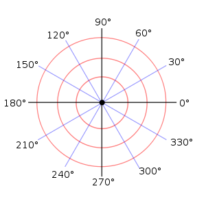
Circumference Holes Processing (Bolt hole circle) also referred to in the manual as PCD (Pitch Circle Diameter). The display’s menu prompts you to answer the following: The work planes, the center location, the bolt circle diameter, the quantity of holes, the starting angle (for the first hole) and the ending angle (for the last hole). This is straight forward enough and you can follow the instructions as written as long as you understand how to specify the correct starting and ending angles.

300px-Polar_graph_paper.svg.png

Use the above diagram to aid in specifying the correct polar coordinates.

Bruce (BGHansen) uses a method so he only has to specify the starting angle and doesn’t have to figure out the ending angle. He adds 1 hole to the required number of holes and enters the same angle for the ending angle as he used for the starting angle. This way you do end up with one more hole location value in the calculated coordinates, but you just ignore that last one. Use whatever method you are most comfortable with.
 
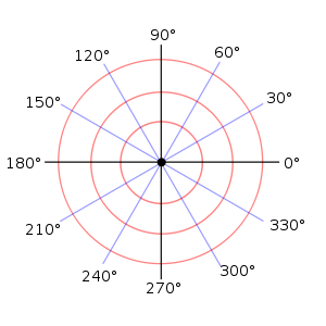
Linear Holes Processing: This is pretty well explained in the manual. Use the same polar coordinate system for specifying angles as when doing a bolt hole circle.
300px-Polar_graph_paper.svg.png
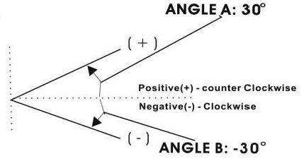
The manual also covers using a negative angle value in this section. This would probably work for the bolt hole pattern as well, but I have not tried it yet.

+ or - angle.jpg

The manual did a pretty good job with this one, but I thought adding these visuals might help. BGHansen was nice enough to send me a copy of his older manual that he had scanned and cleaned up. It's funny, because that older manual has some graphics and information that is not in my new manual! But, there is some stuff in mine that's not in his.

Ted
 
Arc Processing: The prompts and required parameter entry was different on my unit than the instructions in the manual. There was no simple vs smooth functions and no type on my unit. Below, are the prompts when I select Arc Processing:
  • Select plane.
  • Enter arc center location.
  • Enter the arc radius length.
  • Enter the cutting tool diameter.
  • Enter Max. cut. This is the step point to point distance as you position around the arc.
  • Enter start angle.
  • Enter end angle.
  • Select “Rad-Tl or Rad+Tl” (notice one has a “-“ and one has a “+”. The “+” is for and outer arc; the “-“ is for an inner arc.
After entering the above required parameters you will presented with the first location. Move the two work axes until they display “0”. Rinse and repeat until you have worked your way around the arc.
The prompts above seem to be that of the “smooth” arc function since there is no “Type” prompt and there are “Center”, “Start Angle”, and “End Angle” which the smooth function needs. So maybe they have discontinued the simple function.
Note: In the X/Y plane you would most likely be plunging with an end mill for cutting the radius. You would move to a position, plunge cut and retract, move to next position, plunge cut and retract, etc.. With X/Z or Y/Z you would most likely take your cuts with the X axis (if arcing in the Y/Z plane) or Y axis (if arcing in the X/Z plane) and I’m thinking a ball end mill, or cutter with a radius on the cutting edge would give you some pretty satisfactory results since it would minimize the steps and blend the cuts in better than a sharp cornered cutter.

Ted
 
Dang you know is some sharp tools here on forum but not including myself so I need these step by step help.These are things that I want to learn and use,fantastic
 
Please remember as I go through these functions my intent is not to re-write the manual. My goal is only to supplement it by sharing what I have learned, through trial and error, while figuring out how to use the functions in cases where the manual didn’t make sense to me. So, you’ll need to go through the manual yourself, and if you are confused by it, maybe reading what I have learned will help.

Oblique Processing (M1 keypad function): The manual is poor with this one. For starters, “oblique processing”??? I guess I would call it “Cutting Angles”. Here’s my plain language summary of the function. There are basically two modes: X/Y planes and the X/Z,Y/Z planes. With the X/Y plane, you use this function to align the work piece with a dial indicator so you can cut the desired angle with either the X or Y axis plane. When using the X/Z, Y/Z planes you will be either tilting or nodding your head at the desired angle and the processor will calculate the step over distance based on the diameter of your cutting tool to make the series of cuts to cut the whole angle. I didn’t play with this method and only did the X/Y plane since I very seldom tilt or nod my head.

Oblique Processing Diagram.jpg

For the X/Y plane there are only 4 prompts: Select planes, desired angle, move X and move Y. The problem was with specifying the angle. The example in the manual of using 45 degrees does not work. You have to use 180 – 45 or 135 degrees if the work piece is tilted the way it is pictured in the manual (tilted CCW). The 45 degrees only works when the work piece is tilted CW. So, if you tilt the work piece CW, you use an angle between 0 (not tilted at all) to 90 degrees (tilted at a full right angle). When tilting the work piece CCW, you use an angle of 180 (not tilted at all) to 90 (tilted at a full right angle). You can not use negative degrees. I tried. When you press the enter key it changes it to a positive value. If you try doing it the way the manual suggests the Y readout goes in the wrong direction and can not be used.
So, here’s what you do.
  • Roughly line up the work piece at the correct angle.
  • Put a dial indicator on one of the X side edges (like the one closest to you like in the diagram) near one of the corners and zero it.
  • Press the M1 function, select the X/Y planes and specify the angle using an angle determined by my paragraph above.
  • After entering the angle you will be prompted to move X. You can go in either direction (depending on where you have your indicator set up). Direction makes no difference, but you’ll need to move in the direction that has the indicator leaving the surface so a gap forms between the indicator and work piece edge. Move as far as you want. The farther you go probably the more accurate.
  • When done moving X, press the Y key. A value will display on the readout. Move Y until the Y value becomes 0000.0000 At this point, if you have the correct angle, the indicator will read back on zero where you initially set it before moving the X axis.
  • If the reading is off, adjust the work piece and go through the process again until it is within your tolerance.
I can see where this can come in handy if you need an accurate angle cut. It really is quick and easy to set up once you know how.

Ted
 
Hi Ted,

Thanks so much for documenting this in the forum! Your write-up is very easy to read and does a great job explaining the functions.

Bruce
 
A quick PS for owners of Precision Matthews products with factory DROs ... Though the displays and scales are branded Precicon Matthews, they're the spittin' image of TPAC's products. So anything @Technical Ted says about TPAC should apply exactly to PM.

My guess is that ALL of these DRO systems come from the same Chinese factory. I'd be willing to bet that Sino products are also the same. Thanks, Ted!

PS to @utson - you can download a DRO manual from the PM website. Just go to one of their machine tools that has DRO installation as an option. Then scroll down to "Manuals and Documentation" and clock the plus on the right side.
 
Back
Top