- Joined
- Feb 2, 2014
- Messages
- 1,056
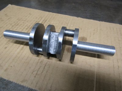
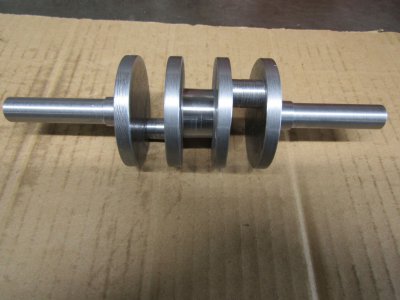
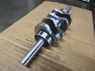
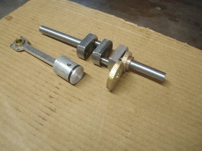
My last engine build was a 90 degree V Twin engine and after some run time I noticed the flywheel was not running as true as it had. The crankshaft was coming apart so a new one was in order. I had made the crank from a 6 piece design glued up pressed together with steel pins. I had used this design before but not with this large a flywheel. I decided to make a 1 piece crankshaft for the added strength and I made some other updates while I had it apart.
All is working fine now the the engine is becoming quite reliable but that brought me to this subject. A friend of mine, upon seeing the new crank asked me to explain to him just how I had made it and show the setups for machining. I thought maybe someone else would also like to see the steps that I use so here it is.
This Crankshaft specs
1 1/2" throw
Two cylinder
One piece steel
And since it would be visible and not inside a crankcase it must have with counter weights and look good.
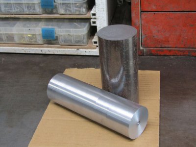
The chunk of steel must be at least 2.25 in diameter and I wanted it 7" long so I made it 7 1/2" long.
The shaft I had was somewhat larger than I needed so I cut it off and reduced the diameter.
That is a hefty chunk there.
I center drilled the shaft in the lathe and moved it to the milling machine where I milled a groove the entire length about 0.020 deep and 1/2" wide.
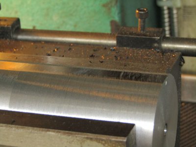
This groove was to be my index for the next operation which was to center drill the offsets for the two throws.
The shaft was secured in the vise vertically and using the original center hole I was able to move over 0.750 each direction and drill the new holes. The shaft was then turned over and the the same thing was done to the other end. The index groove insured that all the holes were in the correct place.
Please excuse the photo as this was the only one I had taken to show that process and it was out of focus.
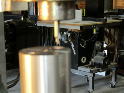
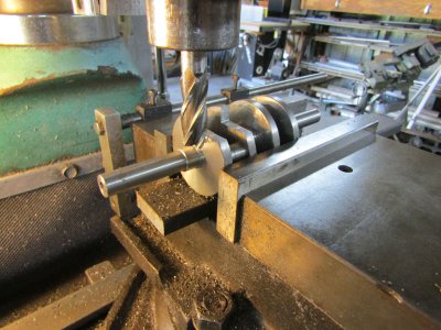
Back in the vise and horizontal I started cutting away bits that I didn't need. The more material that can be removed now will make the job easier later. Here again the index slot kept everything in alignment.
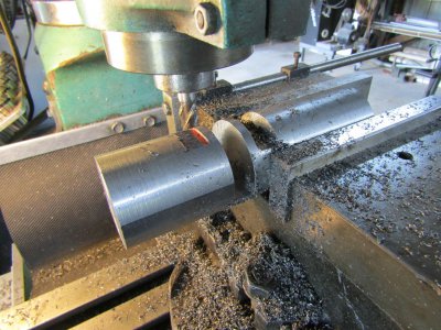
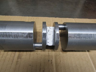
I wanted a 0.625 wide by 1" section in the center of the crank and the rod throws to be 0.560 wide (That was the size of the end mill I had) and the webbing to be 0.250 thick.
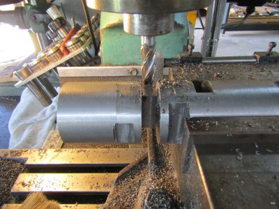
This shows milling off the corners after indexing again.
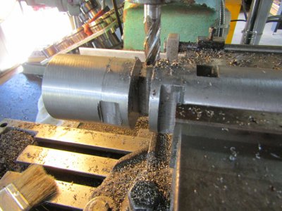
Flip the shaft around and do the same thing on the other end and remove some more material in the center section.
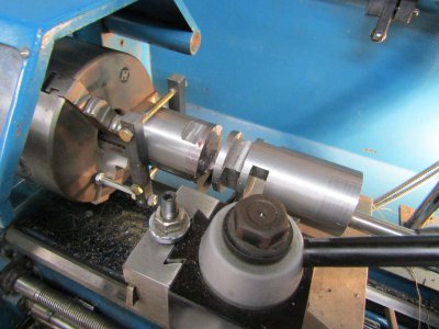
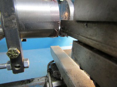
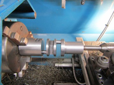
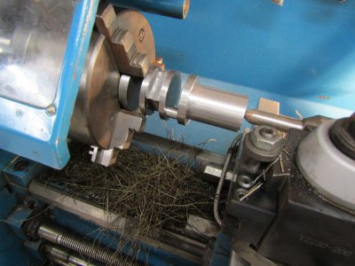
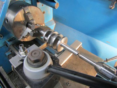
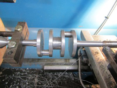
The shaft is now ready for the lathe.
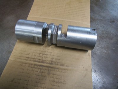
More to come later.
Thanks for looking
Ray

All is working fine now the the engine is becoming quite reliable but that brought me to this subject. A friend of mine, upon seeing the new crank asked me to explain to him just how I had made it and show the setups for machining. I thought maybe someone else would also like to see the steps that I use so here it is.
This Crankshaft specs
1 1/2" throw
Two cylinder
One piece steel
And since it would be visible and not inside a crankcase it must have with counter weights and look good.
The chunk of steel must be at least 2.25 in diameter and I wanted it 7" long so I made it 7 1/2" long.
The shaft I had was somewhat larger than I needed so I cut it off and reduced the diameter.
That is a hefty chunk there.

I center drilled the shaft in the lathe and moved it to the milling machine where I milled a groove the entire length about 0.020 deep and 1/2" wide.

This groove was to be my index for the next operation which was to center drill the offsets for the two throws.
The shaft was secured in the vise vertically and using the original center hole I was able to move over 0.750 each direction and drill the new holes. The shaft was then turned over and the the same thing was done to the other end. The index groove insured that all the holes were in the correct place.
Please excuse the photo as this was the only one I had taken to show that process and it was out of focus.

Back in the vise and horizontal I started cutting away bits that I didn't need. The more material that can be removed now will make the job easier later. Here again the index slot kept everything in alignment.

I wanted a 0.625 wide by 1" section in the center of the crank and the rod throws to be 0.560 wide (That was the size of the end mill I had) and the webbing to be 0.250 thick.

This shows milling off the corners after indexing again.

Flip the shaft around and do the same thing on the other end and remove some more material in the center section.
The shaft is now ready for the lathe.

More to come later.
Thanks for looking
Ray


