-
Welcome back Guest! Did you know you can mentor other members here at H-M? If not, please check out our Relaunch of Hobby Machinist Mentoring Program!
You are using an out of date browser. It may not display this or other websites correctly.
You should upgrade or use an alternative browser.
You should upgrade or use an alternative browser.
Linear Compensation
- Thread starter ddickey
- Start date
- Joined
- Feb 1, 2015
- Messages
- 9,575
If you mean scale calibration, it is reached through the settings menu on your DRO.
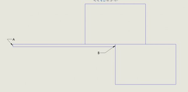
Here is how I did mine. I used two 1/2/3 blocks.The first served as a guide and was clamped to the bed parallel to the axis that I was calibrating, as verified by sweeping the block. The second was clamped to the table and in contact with the first block. I measured the length of a 1" parallel with a micrometer and clamped it to the first block so it was in contact with the second block. I mounted a test indicator in the spindle with the spindle locked and zeroed it on surface A and zeroed the DRO for that axis. Then I removed the parallel and moved to position B so that the indicator was zeroed. Then I read the DRO. The position should equal the measured length of the parallel. If not, adjust the calibration as determined by your DRO manual. Repeat for remaining axes.

Here is how I did mine. I used two 1/2/3 blocks.The first served as a guide and was clamped to the bed parallel to the axis that I was calibrating, as verified by sweeping the block. The second was clamped to the table and in contact with the first block. I measured the length of a 1" parallel with a micrometer and clamped it to the first block so it was in contact with the second block. I mounted a test indicator in the spindle with the spindle locked and zeroed it on surface A and zeroed the DRO for that axis. Then I removed the parallel and moved to position B so that the indicator was zeroed. Then I read the DRO. The position should equal the measured length of the parallel. If not, adjust the calibration as determined by your DRO manual. Repeat for remaining axes.

- Joined
- Feb 1, 2015
- Messages
- 9,575
For calibration purposes, you want to use as large a separation distance as practical. If your separation distance is only an inch or two, rounding errors would mean that it would be possible to be off by several thousandths on 10 or 12" distance. My DRO resolves to .0002". I have a 6" micrometer which measures to .0001" and made the 6" parallel a good choice. I don't have 6" of vertical travel on my mill/drill so stacked two 1/2/3 blocks for a total of 5".
I wouldn't use the mill dials as my distance standard, at least not without verifying first.
I wouldn't use the mill dials as my distance standard, at least not without verifying first.
- Joined
- Feb 1, 2015
- Messages
- 9,575
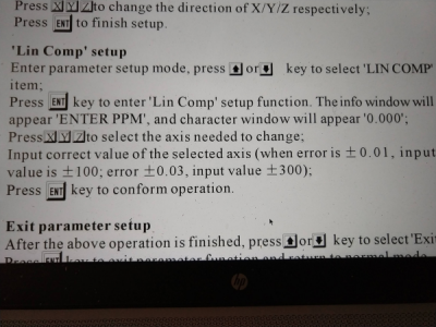
The instructions can be cryptic. My Grizzly DRO appears to be similar to yours. According to the manual, the error is measured in parts per million (PPM). In my case, using a 6" step, a 6.0012" reading would be a .0012" error which would be .0012"/6" x 1,000,000 or 2000PPM. Since the reading is higher than the actual value, I would enter-2000 for the correction factor.
After making the correction, exit and repeat the measurement. The DRO should now agree with the actual distance.
The manual advises using a known standard that is at least one "grade" better than the DRO resolution. For shorter distances, either a gage block or a step gage measured with a micrometer. Since you are actually measuring PPM, the longer the gage the better. A .0001" measurement error in a 1" standard would be 100PPM while in a 5", it would be 20PPM. Consider also that if you have 5 micron scales, the reading resolution is +/- .00016" which factors into your measurement.
- Joined
- Jun 12, 2014
- Messages
- 4,806
In general I would recommend skipping it. Most scales, at least the ones I have purchased come with an accuracy (deviation) record over the measured length or QC length, and you could enter this into the DRO. In most cases the measures accuracy on a 5 micron scale, the acceptable QC limit might be a deviation of +/- 0.0002" of the accepted measured value. On my 1 micron scale I purchased recently the deviation log was far beyond the accuracy of any of my measuring equipment. There is also a difference between the resolution that you can read and the accuracy of the scale/DRO, so they often will give a scale resolution and then the a measured accuracy resolution. At this level of precision, and what your require, I can't see the value of mapping out a scale unless there are significant deviations, i.e. problem with the QC. You also need to look at the reproducibility of the error, so is it a scale resolution issue or a read/interference random error.
I will check scales against a distance measurement by counting dial revolutions over a given travel and comparing that value to the scale, and then back to 0 several times. This will detect any random, or counting errors say from scale alignment. I just did this with a tailstock magnetic scale and couldn't find any tracking difference over a 6" travel, it would always repeat back to 0 within 1 count +/- 0.0002" (thichness of the dial mark).
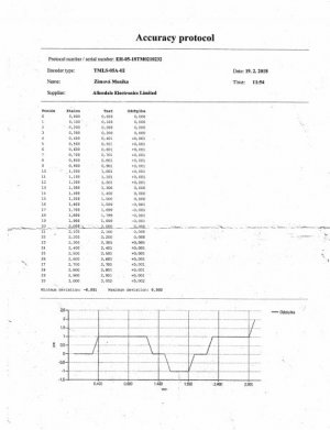
Below is a readout, the values are in mm so the deviation is for the most part +/- 0.001 mm for a 5 micron scale magnetic scale. The Y scale is microns the X axis is distance. The maximum deviation was 0.00008".

- Joined
- Feb 1, 2015
- Messages
- 9,575
The deviation log shows how the scale conforms to to the stated nominal position along its range of travel. For years, I used my Grizzly DRO as it came out of the box, blissfully ignorant of any calibration requirement. A year or so ago, Bob Korves (https://www.hobby-machinist.com/threads/dro-error.64376/#post-534589 post#8) brought the calibration issue to my attention and I decided to check my DRO. Sure enough, there was a calibration routine and all three axes were out. Not a lot, and for small travel distances, well within the limits of other machining errors but over a distance of 10' they could amount to several thousandths. Until recently, I had no way of measuring that would detect this error and it went unnoticed. Now, with a 24" vernier capable of measuring to .001" I can see it.
BTW, I have the tracking readouts for my scales as well and all three scales are within the 5 micron resolution. I did note that the temperature for their measurement was around 20ºC whereas my shop temperature is usually between 15 and 18ºC.
BTW, I have the tracking readouts for my scales as well and all three scales are within the 5 micron resolution. I did note that the temperature for their measurement was around 20ºC whereas my shop temperature is usually between 15 and 18ºC.


